Parker EME
Compax3 device description
192-120100 N16 C3I10T10 - December 2010
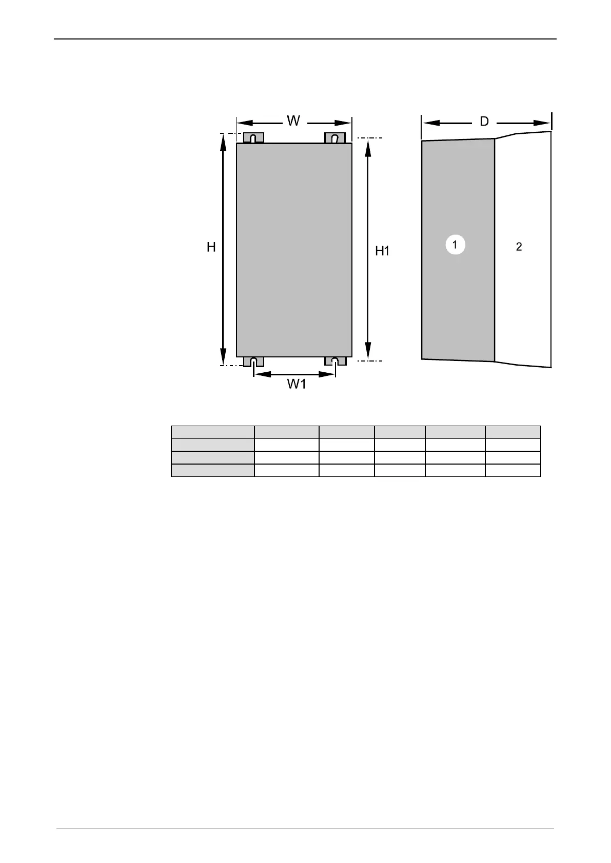
3.9.3. Mounting and dimensions C3H
The devices must be mounted vertically on a level surface in the control cabinet.
(1): Electronics
(2): Head dissipator
H H1 D W W1
453mm 440mm 245mm 252mm 150mm
C3H090V4
668.6mm 630mm 312mm 257mm 150mm
720mm 700mm 355mm 257mm 150mm
Mounting:4 screws M6
During operation, the device radiates heat (power loss). Please provide for a
sufficient mounting distance below and above the device in order to ensure free
circulation of the cooling air. Please do also respect the recommended distances of
other devices. Make sure that the mounting plate is not exhibited to other
temperature influences than that of the devices mounted on this very plate.
If two or more devices are combined, the mounting distances are added.
 Loading...


