Compax3 device description
C3I10T10
192-120100 N16 C3I10T10 - December 2010
3.5 PSUP/Compax3M Connections
Front connector
In this chapter you can read about:
............................................................................................................... 40
Connections on the device bottom ................................................................................... 41
Connections of the axis combination................................................................................ 42
Control voltage 24VDC PSUP (mains module) ................................................................ 43
Mains supply PSUP (mains module) X41......................................................................... 44
Braking resistor / temperature switch PSUP (mains module) ........................................... 46
Motor / motor brake Compax3M (axis controller) ............................................................. 48
Safety technology option for Compax3M (axis controller)................................................. 49
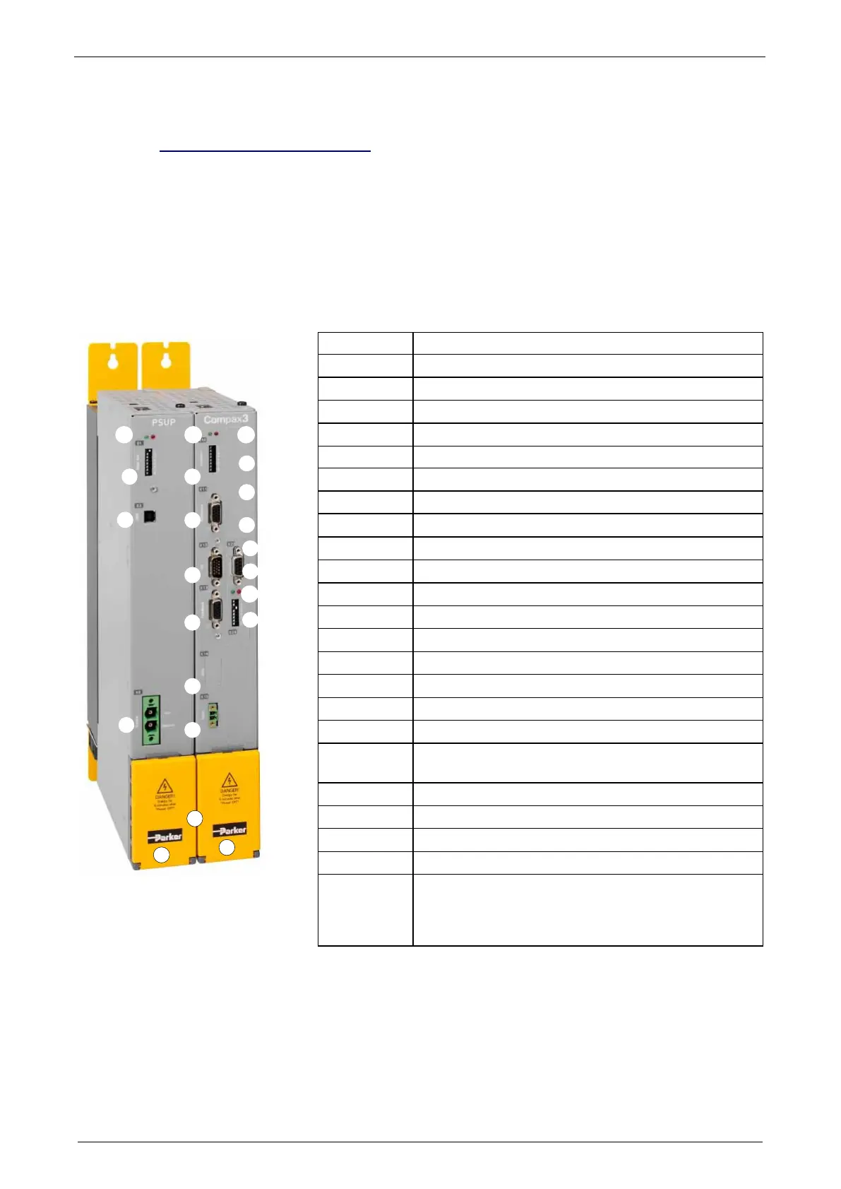
3.5.1. Front connector
X22
X21
X20
LED3
X15
X13
X12
X11
S10
LED2
X9
X3
S1
LED1
S24
LED4
X24
X23
X14
1
P
M
LED1 Status LEDs Mains module
S1 Basic address
X3 Configuration interface (USB)
X9 Supply voltage 24VDC
LED2 Status LEDs of the axis
S10 Function
X11 Analog/Encoder
X12 Inputs/Outputs
X13 Motor position feedback
X14 Safety technology (option)
X15 Motor temperature monitoring
LED3 HEDA LEDs
X20 HEDA in (Option)
X21 HEDA out (Option)
X22 Inputs Outputs (Option M10/12)
X23 Bus (option) connector type depends on the bus
system!
X24 Bus (option) depends on the bus system!
LED4 Bus LEDs
S24 bus settings
1 Behind the yellow protective covers you can find the
rails for the supply voltage connection.
Supply voltage 24VDC
 Loading...


