Chapter E: Basic repair procedures 2 Basic repair procedures
Technical manual Planmeca PlanMill 40 99
Figure 80: Drawer slide release button
9. Press the black release buttons on the sides and pull forward to fully remove the
drawer assembly from the milling unit.
Install
1. Reinstall the drawer onto the drawer slides, carefully align each drawer rail into its
corresponding mate and reinsert the slides into themselves.
It is normal for there to be some additional friction when first reassembling the drawer slides
as the ball bearings are initially sliding rather than rolling. However, be very careful not to
force the rails back together without being properly aligned as this can bend and damage
the rail requiring it to be replaced. Once fully inserted the drawer should slide freely in both
directions.
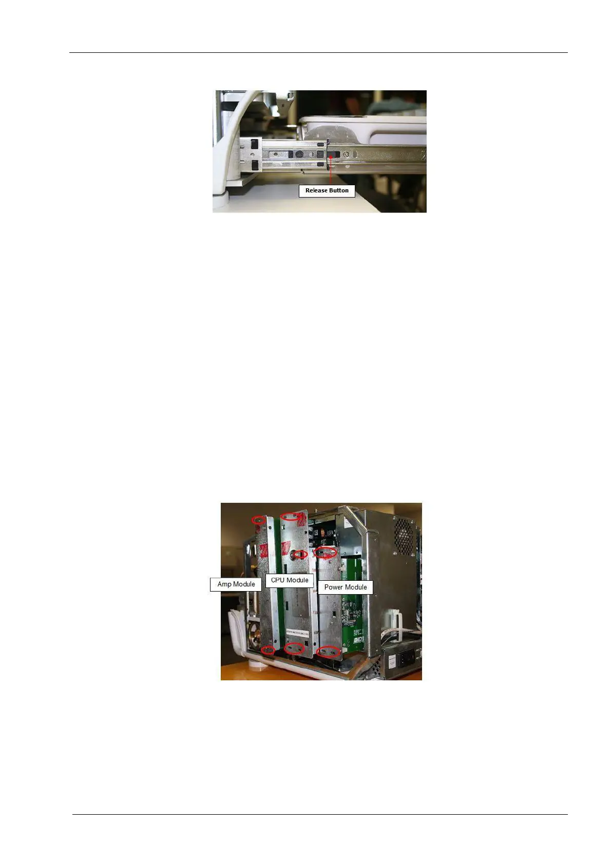
2.2 Electronics box
The electronics box consists of upper and lower sections; the upper section holds the
three field serviceable modules. The following procedures will illustrate how to properly
access these three modules.
Figure 81: Mill electronic box modules