7 Mechanical design Chapter A: General and technical data
16 Planmeca PlanMill 40 Technical manual
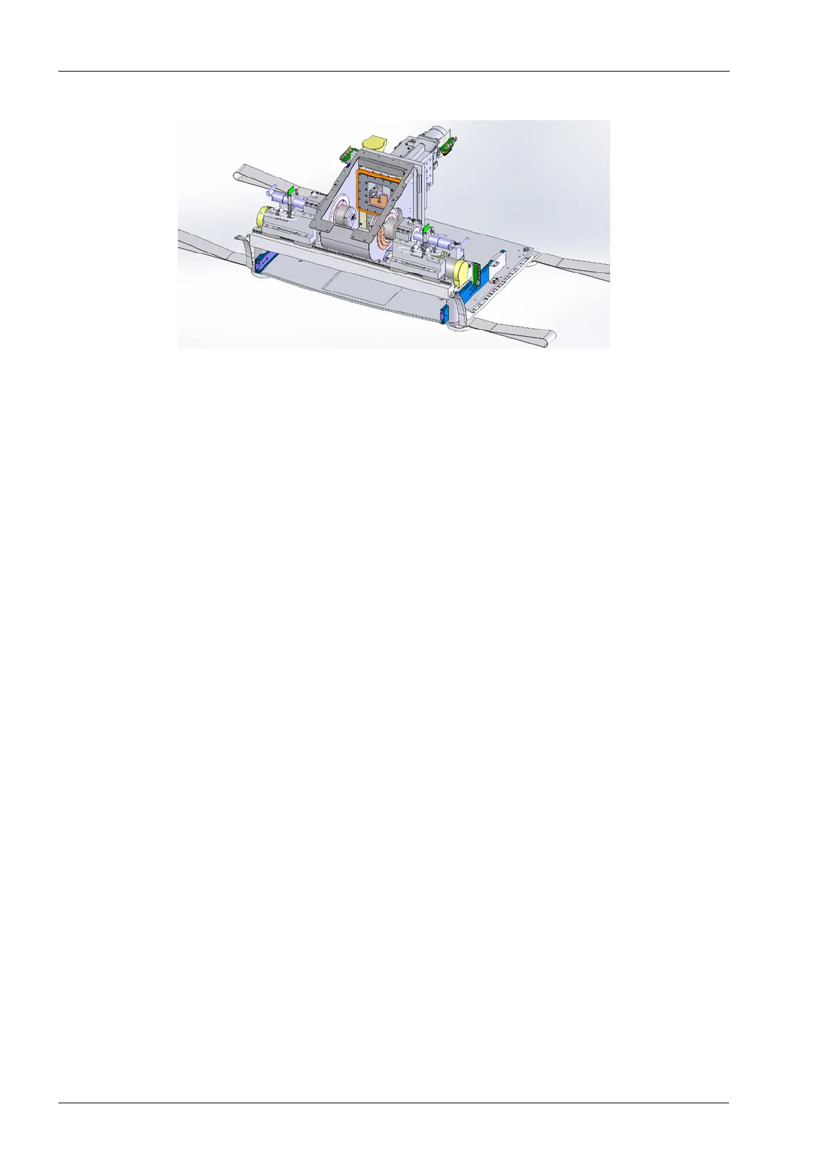
Figure 1: Motion base assembly
7.2 Electronics box
The electronics box is located in the right rear of the machine and consists of an upper and
lower section. The lower section contains the A/C input power conditioning components
and supports A/C, Ethernet, and USB cabling connections. Additionally, there is a
transformer and rectifier circuit to provide voltage for driving the servo motors and
spindles. The upper box mounts atop the lower and provides three dedicated slots to
insert the computer module (CPU module), amplifier module (Amp module), and power
supply module. Each module plugs into the backplane board. This board provides power
and all input and output signals required to operate each module, thus eliminating any
individual cabling connections to the modules.
The opposite side of the backplane board supports cable connector receptacles used to
connect various components via cables to the electronics box. These connector
receptacles are made available through precisely aligned openings in the rear of the box.
The net result of this design is that the cabling connections are made at assembly, and
they do not need to be disconnected if one or more of the modules require servicing. This
greatly increases the serviceability and the robustness of the design. Additionally, the
upper box contains a cooling exhaust fan positioned to take advantage of the natural heat
transfer and adequately cool all electronic components located inside the electronics box
assembly.
The computer stack module incorporates several computer boards stacked upon one
another using the PC104 interface bus. Included in this stack are the single board
computer (SBC), motion controller board, DSP spindle controller/interface board, and
computer hard drive. The SBC is the host computer that handles the windows operating
system; it runs the PlanMill 40 application in addition to handling all networking operations.
The motion controller board is DSP-based and handles the real time control of the four
servo motors. It is under the direct control of the SBC via the PlanMill 40 application. The
DSP spindle controller/interface board provides direct control of the spindle motors and
low level monitoring of all sensors. FPGA coded chips and Firmware are both used to
monitor and control these components. This board is also under direct control of the SBC
via the PlanMill 40 application. Additionally, this board handles all the cabling connections
from the SBC, hard drive, and motion controller board and it connects the signals to the
backplane board.
The amplifier module contains the four servo amplifiers which are mounted to a PC board.
This board plugs directly into the backplane. The purpose of the servo amplifier is to take
the low voltage TTL signals from the motion controller board and amplify them to drive the
servo motors which operate at a nominal 42 Vdc. Because the amplifier components
generate heat, there is also a heat sink plate that is one side
of the upper electronics box.