Chapter E: Basic repair procedures 2 Basic repair procedures
Technical manual Planmeca PlanMill 40 97
Tools required
• metric Allen key set
Removal
1. Remove the top cover, see section 2.1 "Mill covers" on page 94.
2. Remove the three screws securing the side panel (two on top, one in front) to the
frame rail.
3. Pull side cover forward and up to disengage from rear cover, lift clear of the machine.
Install
1. Install the side cover by sliding the rear of the side cover at an angle down and to the
inside of the rear cover.
2. Carefully push side cover down while aligning it into the trim that curves next to the
drawer handle.
3. Secure the side cover with three screws (two on top, one in front) to the frame.
4. Install the top cover, see section 2.1 "Mill covers" on page 94.
2.1.3 Rear cover
The milling unit is designed such that removal of the rear cover is only required for more
advanced repairs or in the event that the top cover needs to be removed but the drawer
and lid cannot be opened.
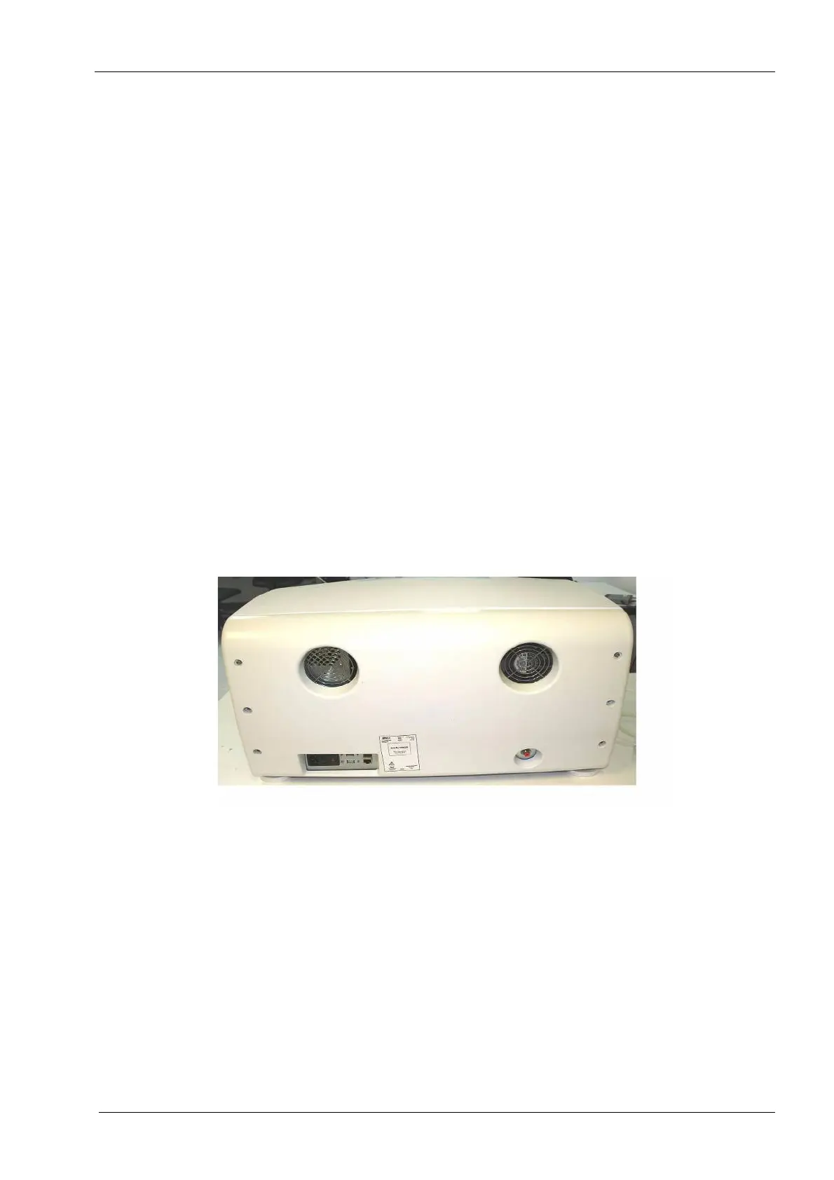
Figure 78: Rear cover
Removal
1. Remove the power cord and air supply line from back of mill.
Properly power down the operating system prior to disconnecting the power cord.
The air line must be released of pressure prior to disconnecting the hose or damage
to the orange one-touch fitting can occur.
2. Remove six screws from the back and carefully detach the rear cover from the mill
chassis.
3. Disconnect the fan connection.