2 Basic repair procedures Chapter E: Basic repair procedures
100 Planmeca PlanMill 40 Technical manual
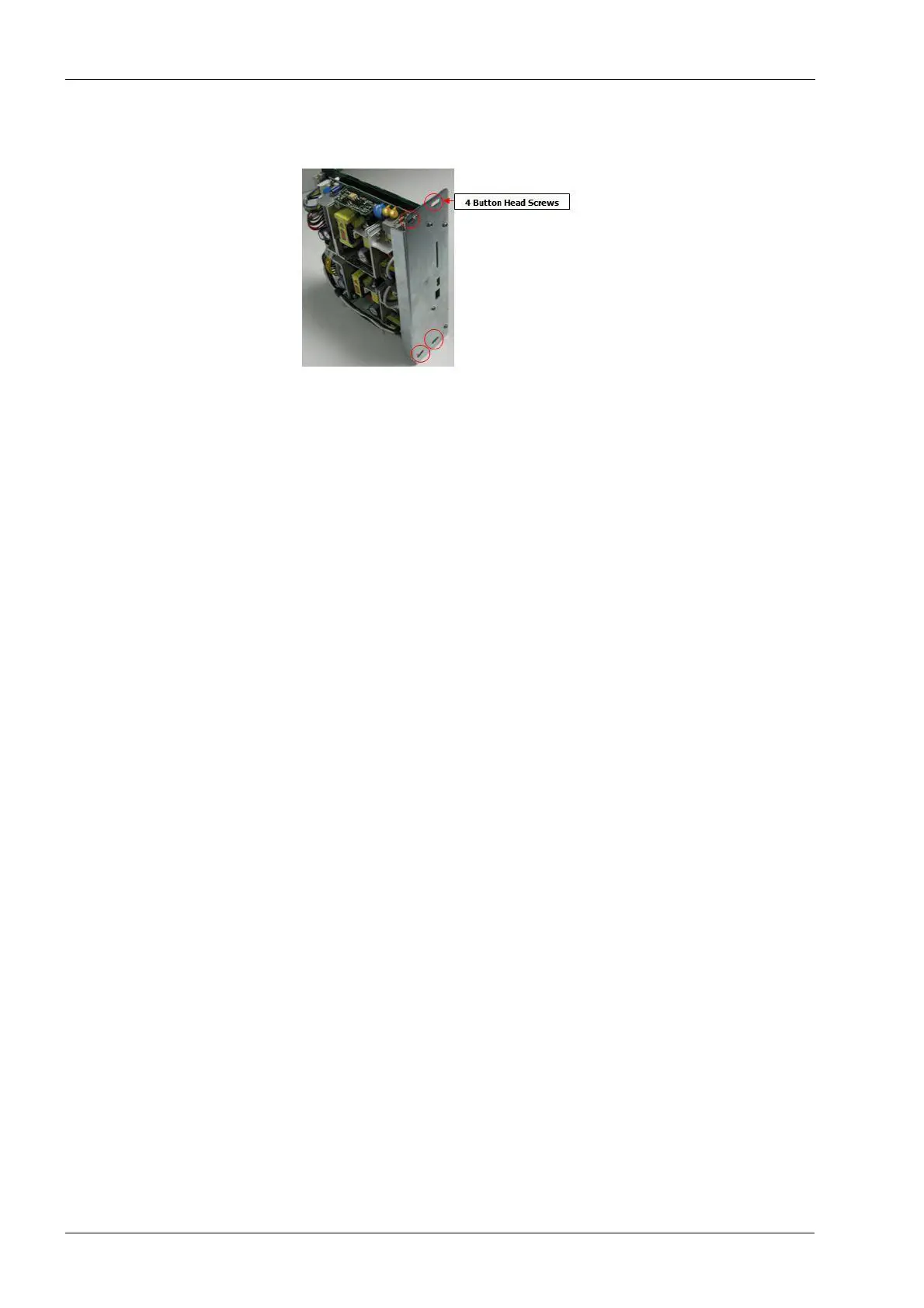
2.2.1 Power supply module
Figure 82: Power supply module
Tools required
• metric Allen key set
Components of the Power module can be damaged by electrostatic discharge. Be
sure to ground yourself properly before handling these components.
Removal
1. Remove the top cover and right side panel; see section 2.1 "Mill covers" on page 94.
2. Power the milling unit down.
3. Be sure to switch off the power at the power entry module or unplug the power cord
before removing the power supply module.
4. Remove the four button-head screws securing power module to chassis using a 2 mm
Allen key.
5. Grab top and bottom edges of power module and slide module out of upper
electronics box.
Install
1. Position power module in upper electronics box. Carefully align the top and bottom
card slot guides.
2. Slide power module in place, it should slide freely until the edge connector interfaces
the backplane connector. At this point some resistance will be felt. Apply an even firm
force to the face of the module to seat it fully.
3. Secure power module in upper electronics box with four button head screws using the
2 mm Allen key.
Verify
1. With right side cover off, plug in system and enable AC power.
2. Ensure that the +5VSTDBY and heartbeat LEDs are lit.
3. Turn on power supply. Fan should turn on.
4. Ensure that all LEDs are lit:
The following legend defines the meaning of each LED as displayed top to bottom.