7 Mechanical design Chapter A: General and technical data
18 Planmeca PlanMill 40 Technical manual
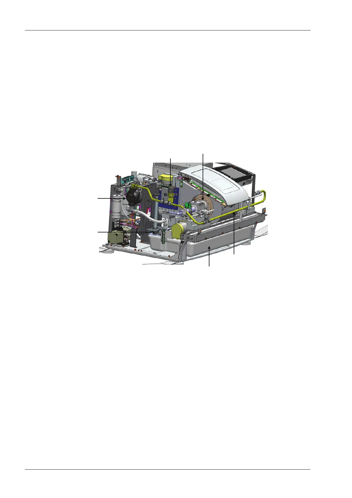
The plastic fluid tank is positioned in a drawer below the grind chamber. The tank is sized
to allow extended operation of the milling unit without servicing, typically 3 hours. Tank ID
sensors detect tank presets. Additionally there is a sensor providing verification that the
drawer is either open or closed. This drawer is accessible to the operator for servicing by
entering the proper maintenance routine. Upon entering this routine, the drawer is
unlocked and the pump suction line and fluid level sensors are raised out of the tank, thus
freeing the drawer and tank to be opened for service. The high and low water level
sensors provide coolant level indications to the operator.
The pump assembly is located in the left rear of the mill and utilizes a self-priming
diaphragm pump. This pump is sized to conservatively deliver adequate coolant pressure
and flow for the grinding process. Mounted on the discharge side of the pump is a
pressure switch that provides a feedback signal indicating adequate pressure for milling.
Figure 4: Coolant circulation system
7.4 Pneumatics system
Several components on the milling unit require pressurized air to operate. The control and
use of pressurized air is known as the pneumatics system. The source of the pressurized
air is external to the milling unit and is provided via a supply line connected to the rear of
the machine. The quality of the provided air should fulfill the air purity requirements (refer
to section 5 "Technical specifications" on page 12). Additionally, the pressure and flow
should be adequate to provide a minimum of 3.5 bar (50 psig) at 60 l/min (0.06 m
3
/min, 2
CFM).
Major components of the pneumatics system include the separator, filter and regulator
assembly, solenoid control valves, and pneumatic components. The incoming air is
passed through an on-board conditioning system to provide a minimal amount of
protection from a poor quality air source. These components are specifically: a water
separator unit (to remove liquid water droplets from the incoming air), a filter unit, a micro
filter unit, and a regulator assembly. The two filter units ensure all particulates beyond a
specific size are removed from the supply air, and the regulator reduces the incoming
pressure to 3.5 bar (50 psi) for on board use.
Pump
assembly
Coolant
pressure
switch
Spindle housing
& nozzle caps
Float
switches
& suction
assembly
Fluid tank
Tubing