Chapter A: General and technical data 7 Mechanical design
Technical manual Planmeca PlanMill 40 19
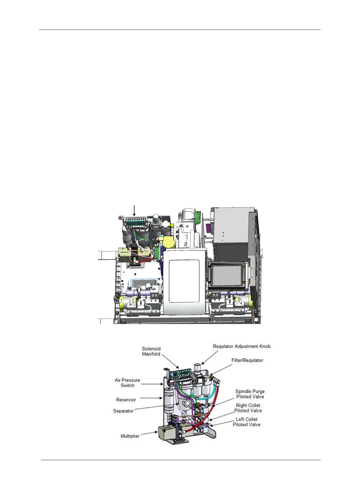
Control of the air is handled by the bank of electrically driven solenoid valves mounted on
a common manifold. Each solenoid is digitally controlled by the computer and can provide
pressurised air on demand to the pneumatic component, which is typically an air cylinder
that is connected by silicon tubing supply line. Each air cylinder’s rate of operation can be
fine-tuned by using manually adjustable inline flow control valves that can control the
volumetric flow to and/or from the cylinder, thus controlling the rate of extension and
retraction. Opening and closing the spindle collets require significantly higher pressure
than other components, specifically 6.9 bar (100 psi). This higher pressure is obtained by
using a component called a pressure multiplier. The pressure multiplier uses the 3.5 bar
(50 psig) supply air to drive itself and compress an additional stream to 6.9 bar (100 psig).
This higher pressure air flow is controlled by two separate piloted control valves. The
piloted control valve is similar to an electrically driven solenoid valve, except the open/
close signal is provided by supplying pressurized air to the control port on the valve. This
control air is supplied by one of the manifold-mounted solenoid valves. The net result is
that all pneumatic operations are controlled via an electric solenoid valve mounted on the
manifold. In the case of the collets, these valves control the piloted valves which control
the high pressure air used to actuate the collets on the spindles. Additionally, a third
piloted valve is used to provide the purge air to the spindle and spindle motor assembly.
This piloted valve is also controlled by a manifold solenoid valve. The piloted valve is used
in this case to provide the 60 l/min (0.06 m
3
/min, 2 CFM) flow rate not capable by the
manifold valve alone.
Figure 5: Pneumatic system
Figure 6: Pneumatic assembly