Technical manual Planmeca PlanMill 40 93
Chapter E: Basic repair procedures
1 Overview
This chapter provides detailed instructions for field-level servicing of the Planmeca
PlanMill 40. Each procedure is illustrated and lists the tools required.
For identification of replacement parts with Planmeca part numbers, refer to the
Calibration and maintenance kits for Planmeca PlanMill 40 milling unit, Export News 13/
2014 or contact Planmeca After Sales.
Service technicians should not attempt to remove or repair any component not covered in
the following instructions. Repair beyond the level shown in this manual is restricted to
authorized Planmeca service centers.
Always disconnect all power sources from equipment before beginning any repair
procedures.
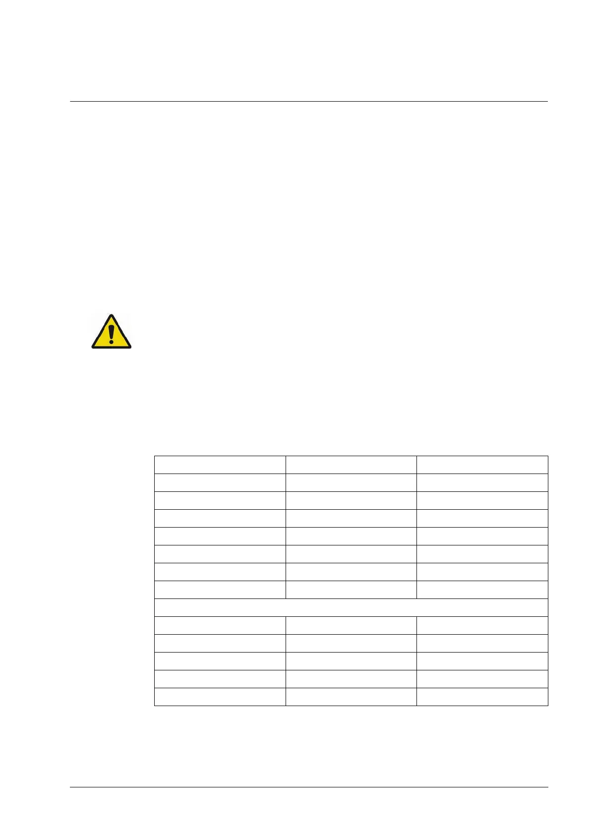
Unless otherwise specified use the torque presented in the following table to secure socket
head screws on used on the milling machine. For button head and flat head screws, use
the torque setting for the screw one size smaller.
Example
Torque for a M3 button head screw = 0.6 nm (5 in-lb).
Table 22: Torque per fastener size
Screw (size) Torque (SI) Torque (English)
M2-.40 0.3 nm 2.625 in-lb
M2.5-.45 0.6 nm 5 in-lb
M3-.50 1.1 nm 10 in-lb
M3.5-.60 1.7 nm 15 in-lb
M4-.70 2.6 nm 23 in-lb
M5-.80 5.2 nm 46 in-lb
M6-1.0 9.0 nm 80 in-lb
UNC 2-56 0.4 nm 3.5 in-lb
UNC 4-40 0.9 nm 8 in-lb
UNC 6-32 1.6 nm 14 in-lb
UNC 8-32 2.8 nm 25 in-lb
UNF 10-32 4.7 nm 42 in-lb