2 Basic repair procedures Chapter E: Basic repair procedures
168 Planmeca PlanMill 40 Technical manual
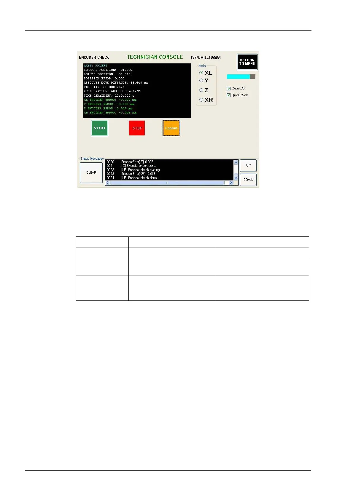
Figure 180: Encoder check
9. Select the Axis: XL or XR as appropriate. Unselect Check All. Select Quick Mode.
Select the START button. After a few minutes, the encoder error for the selected X-
axis will be printed in the text box in the upper left corner of the screen. See the
following table below for encoder error guidelines.
2.13.2 Y-axis servo motor and coupling
Use this procedure for replacing either the Y-axis servo motor or the servo coupling.
Tools required
• 2.5 mm, 4 mm and 5 mm Allen keys
• flat head screwdriver
Removal
1. Remove top cover and left and/or right side panels as required, see section 2.1 "Mill
covers" on page 94.
2. Power down the milling machine and disconnect AC power source.
3. Disconnect Y-axis servo motor power cable from the interconnect board.
4. Disconnect servo motor hall-effect sensor cable from the interconnect board.
5. Disconnect servo motor encoder cable from the interconnect board.
6. Remove (2) M6 flat head Allen screws from the top and side of the Y-axis which
secure the motor mount to the black Y-tube.
Table 4: Encoder error guidelines
Encoder error Problem Solution
0 to 0.015 Acceptable encoder error. No action required.
0.015 to 0.100 Weak servo, defective encoder,
and/or defective cable.
Replace servo motor and retest.
Replace cable if needed.
0.100 or greater Loose motor coupling, defective
encoder, and/or defective
cable.
Tighten motor coupling and retest.
Replace servo motor and/or cable
if needed.