2 Basic repair procedures Chapter E: Basic repair procedures
182 Planmeca PlanMill 40 Technical manual
9. Verify proper operation by the following: Move the Z-axis up to its limit, verify the LED
on the limit sensor goes off once the flag has entered the sensor. Once the LED has
turned off, verify the ‘L’ is displayed to the right of the Z-axis position value in the Axis
Positions Box, this indicates the limit sensor is activated.
10. Move the carriage down off the sensor, the LED on the sensor should illuminate and
the ‘L’ on the display should disappear.
11. Replace right side panel and top cover.
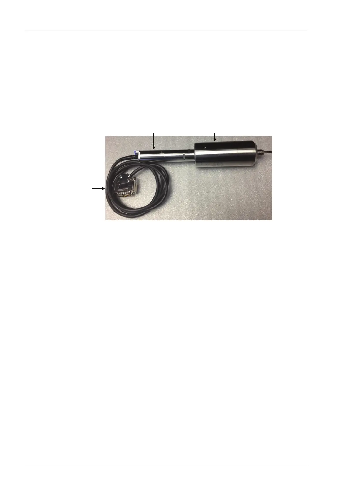
2.13.9 Spindle and spindle motor
Figure 195: Spindle, spindle motor and spindle motor cable
Tools required
• small adjustable crescent key
• two 22 mm narrowed flat open end keys
• metric Allen key set
• 3.175 mm (1/8”) pin key
• wire cutters
Removal
1. Power down the mill.
2. Remove top and either left or right panel as required, see section 2.1 "Mill covers" on
page 94.
3. If the spindle itself needs to be removed use the manual override on the solenoid
valve to take out the burrs from collects.
4. If the right side spindle assembly needs removal, remove the LCD using the
procedure in this service manual.
If the spindle motor cable needs to be replaced with the motor, perform the next five steps
before continuing. Generally, if the spindle motor needs to be changed then the motor cable
can be left in place.
5. Use wire cutters to remove the cable ties securing the spindle motor cable.
6. Note the routing of the cable around the machine. Clip any remaining cable ties.
7. Remove the cable restraint plate from the electronics box, see section 2.2.6 "Cable
restraint plate" on page 108.
Spindle
motor
cable
Spindle motor
Spindle