Chapter E: Basic repair procedures 2 Basic repair procedures
Technical manual Planmeca PlanMill 40 183
8. Using a flat screwdriver, remove the two restraining screws securing the electronic
connector to the electronic box.
9. Disconnect the cable from the electronic box.
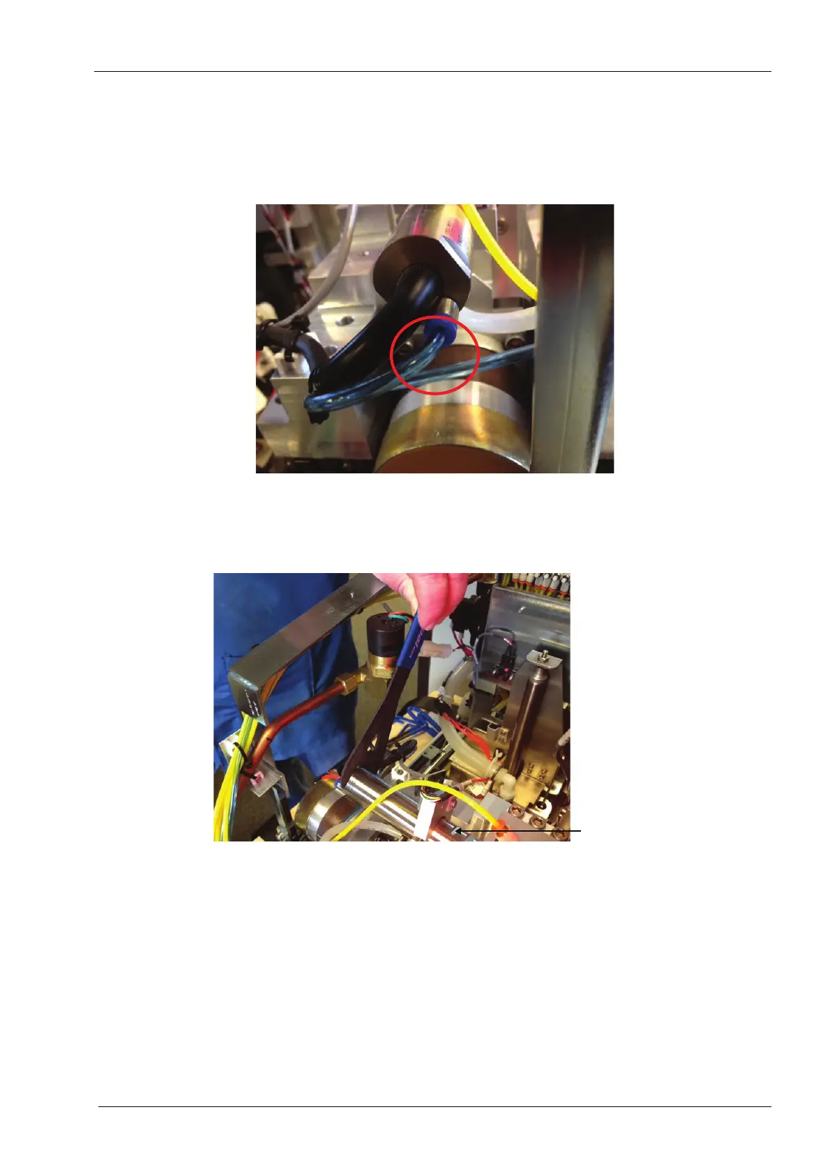
10. Remove blue tubing from one-touch fitting on the rear of the spindle motor.
Figure 196: Remove blue tubing
11. Manually push carriage inboard toward the grind chamber.
12. Place one of the 22 mm flat open end keys on the wrench flat on the motor and the
other one on the flat just the other side of the accelerometer mount.
Figure 197: Disconnecting spindle motor cable
13. Loosen the cable to motor connector by turning anticlockwise with the key on the end
flat while holding the key on the middle flat in place.
Place second
22 mm flat
open end
wrench here