Chapter E: Basic repair procedures 2 Basic repair procedures
Technical manual Planmeca PlanMill 40 119
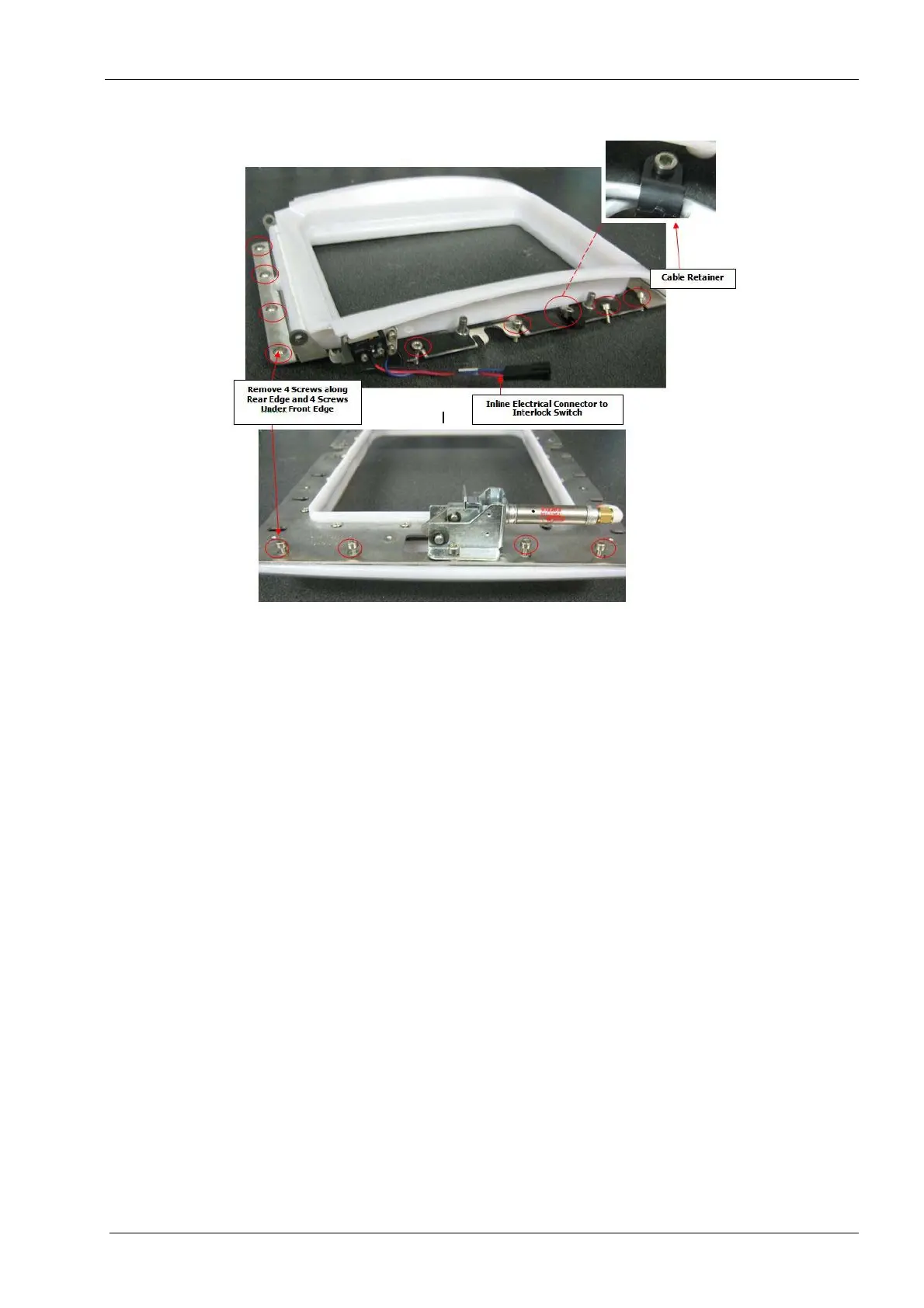
Figure 109: Lid adapter assembly
9. Lift the lid/adapter slightly and shift left then up to lift the assembly clear of the mill.
Install
1. Position the lid/adapter assembly on the grind chamber over the screws and slide it
into place.
2. Secure the assembly by tightening the side screws (5 pcs per side), position the cable
retainers in the same location as when they were removed.
3. Install (4) M3 screws at bottom of lid/adapter assembly.
4. Install (4) M3 screws at top of lid/adapter assembly.
5. Reconnect the air cylinder knuckle to the hinge bracket and secure with the clip-ring.
6. Reinstall the LED boards, see section 2.3.5 "LED boards" on page 124.
7. Route LED and switch wiring in place and secure with wire ties.
8. Connect the two inline electrical connectors on left and right sides of lid/adapter
assembly to the interlock switches.
9. Connect pneumatic tube fitting to latch air cylinder fitting.
10. Verify proper operation by accessing the Open Lid tools in the software or by using
the manual override button on the lid open solenoid.
Make sure the lid operates freely and smoothly with no rubbing on the adapter. Also verify
the latch engages easily and fully.
11. Replace mill covers, see section 2.1 "Mill covers" on page 94.
2.3.2 Lid
The grind chamber lid can be replaced independently of the adapter.