2 Basic repair procedures Chapter E: Basic repair procedures
158 Planmeca PlanMill 40 Technical manual
• Depress the button on the open tool changer solenoid to energize the air cylinder
opened hold the button down.
• Depress the button on the close tool changer solenoid and release the other button.
Example 3
If the tool changer is in between:
• Manually close the tool changer and follow procedure above.
10. Once proper operation is verified on all operations, reinstall rear, left side panel and
top covers, see section 2.1 "Mill covers" on page 94.
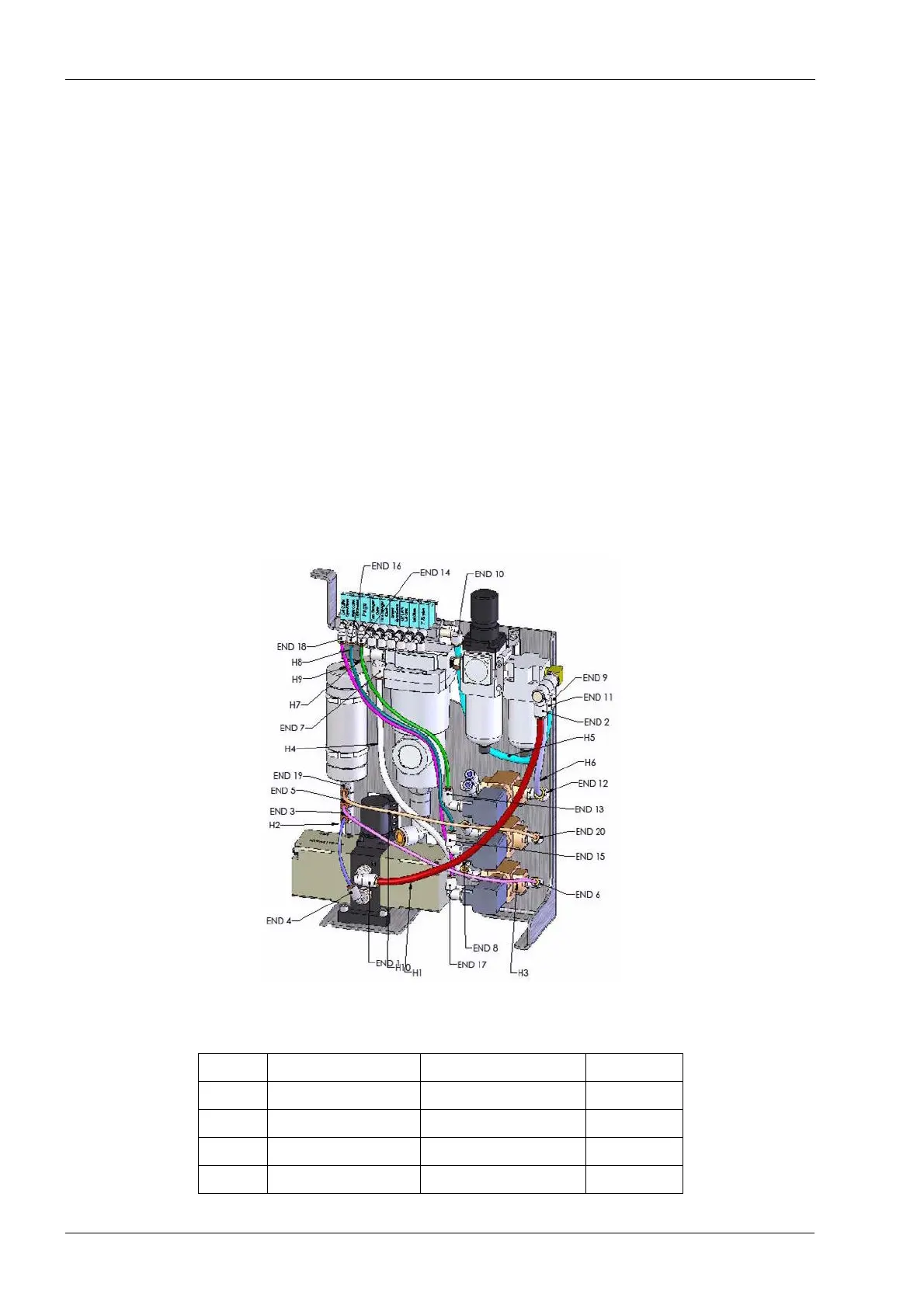
2.12.2 Pneumatics tubing routing
Should any of the tubing on the Pneumatics assembly become damaged or otherwise
require replacement the following diagram can be used for reference
• If required remove pneumatics assembly from the mill, see section 2.12.1
"Pneumatics assembly" on page 155.
• Refer to the table and image below for details on tubing sizes, lengths and routing.
Figure 169: Pneumatic tubing routing
Table 3: Pneyumatic tubing, sizes and lenghts
Tubing From/To Tubing OD (SAE) Lenght
H1 END 1 / END 2 6.35 mm (1/4”) 304 mm
H2 END 3 / END 4 3.18 mm (1/8”) 436 mm
H3 END 5 / END 6 3.18 mm (1/8”) 210 mm
H4 END 7/ END 8 6.35 mm (1/4”) 290 mm