2 Basic repair procedures Chapter E: Basic repair procedures
154 Planmeca PlanMill 40 Technical manual
5. Verify leak free operation and correct any problems.
6. Verify the pump pressure signal is operational and turns on and off with the pump.
The pressure switch signal is shown in the Mechanical Control box next to: PUMP PRESS:
ON and is shown as either on or off.
7. Reinstall the left side panel and top cover.
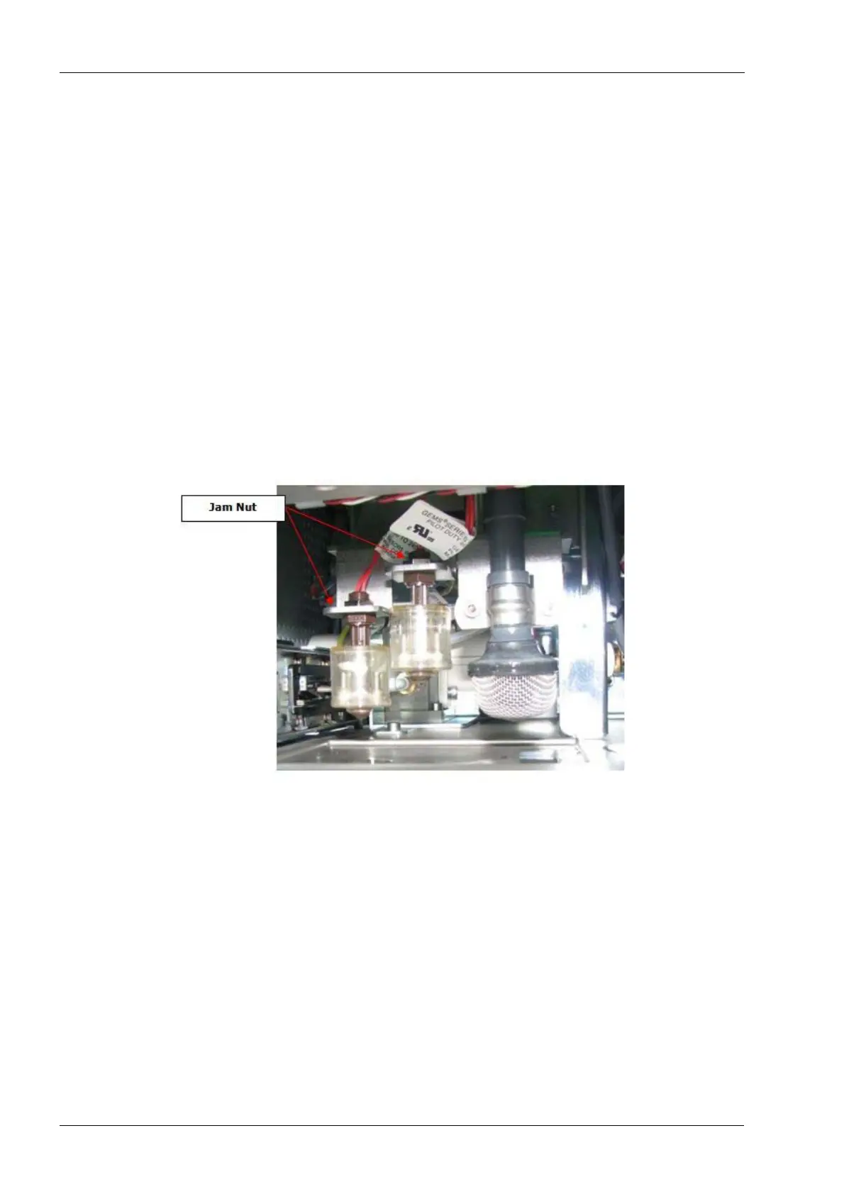
2.11.3 Float switch
There are 2 float switches located on the drawer lock bracket. The outboard float switch is
for low coolant level detection and the inboard (higher) float switch is for full coolant level
detection. Additionally, the suction line has a removable mushroom style strainer installed
as final protection for the pump system against foreign debris that could damage the pump
or clog the water lines.
Tools required
• small crescent (adjustable) key
Figure 164: Float switch
Removal
1. Remove the top cover, left side panel and the drawer assembly, see section 2.1 "Mill
covers" on page 94.
2. Disconnect the in-line electrical connector for the float switch to be removed (mark
connectors if replacing both switches to ensure correct connection and function of
new switches).
3. Use the crescent key and loosen the jam nut securing the float switch to the bracket.
4. Lower the float switch free of the bracket, feed the electrical cable down through the
mounting hole.
Install
1. Feed cable up through mounting bracket.
2. Install jam nut over cable and onto float switch, tighten nut snug.