Chapter E: Basic repair procedures 2 Basic repair procedures
Technical manual Planmeca PlanMill 40 155
Do not over tighten the jam nut as the threads on the float switch are plastic and
can easily be stripped.
3. Reconnect the in-line electrical connection.
2.12 Pneumatics system
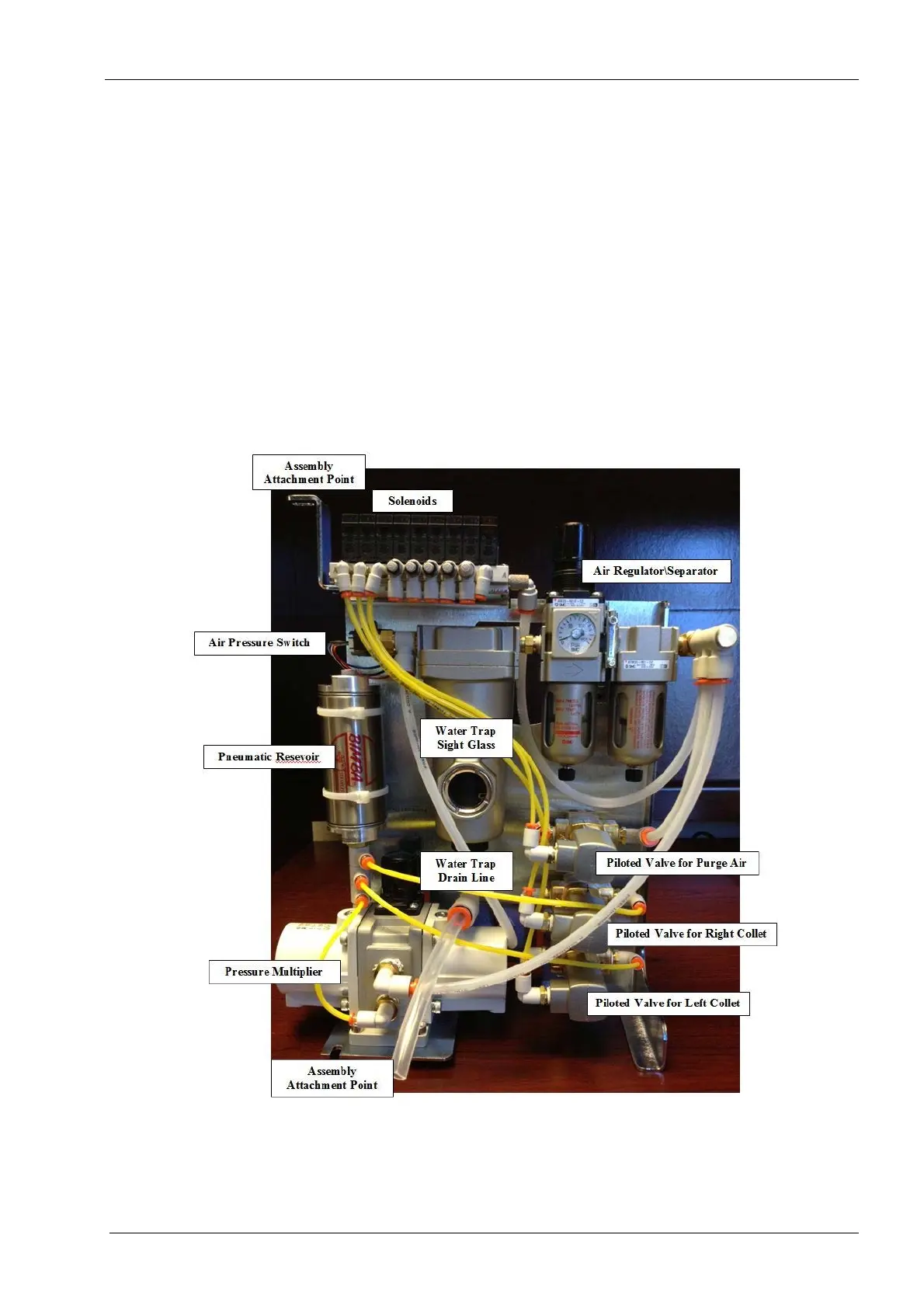
2.12.1 Pneumatics assembly
The pneumatics assembly is located in the back left portion of the machine and can be
replaced as a unit if multiple component failures have occurred. However, if the failure can
be reduced to a single component then changing the component is generally much easier
than changing the entire assembly. Use the procedure below if removal of the entire
assembly is required.
Figure 165: Pneumatic assembly
Tools required
• metric Allen key set
• small diagonal cutters