2 Basic repair procedures Chapter E: Basic repair procedures
124 Planmeca PlanMill 40 Technical manual
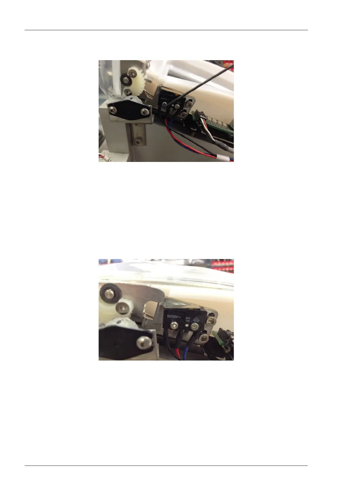
4. Use a 1.5 mm Allen key to remove the mounting screws.
Figure 116: Removing interlock switch
5. Disconnect the cable connector from the cable harness connector.
Install
1. Install the new interlock switch with the mounting screws using the 1.5 mm Allen key.
2. Connect the cable connector to the cable harness connector.
3. Close the lid and verify that the lever arm of the switch fully depresses the orange
actuator button.
4. Then loosen the screws and adjust switch position if need to insure proper switch
function.
Figure 117: Switch installed and lever arm pressing actuator button
2.3.5 LED boards
There are two LED boards which illuminate the grind chamber adapter using multi-colored
LED’s. The left and right boards are serviceable individually; the procedure is the same for
each side.