2 Basic repair procedures Chapter E: Basic repair procedures
104 Planmeca PlanMill 40 Technical manual
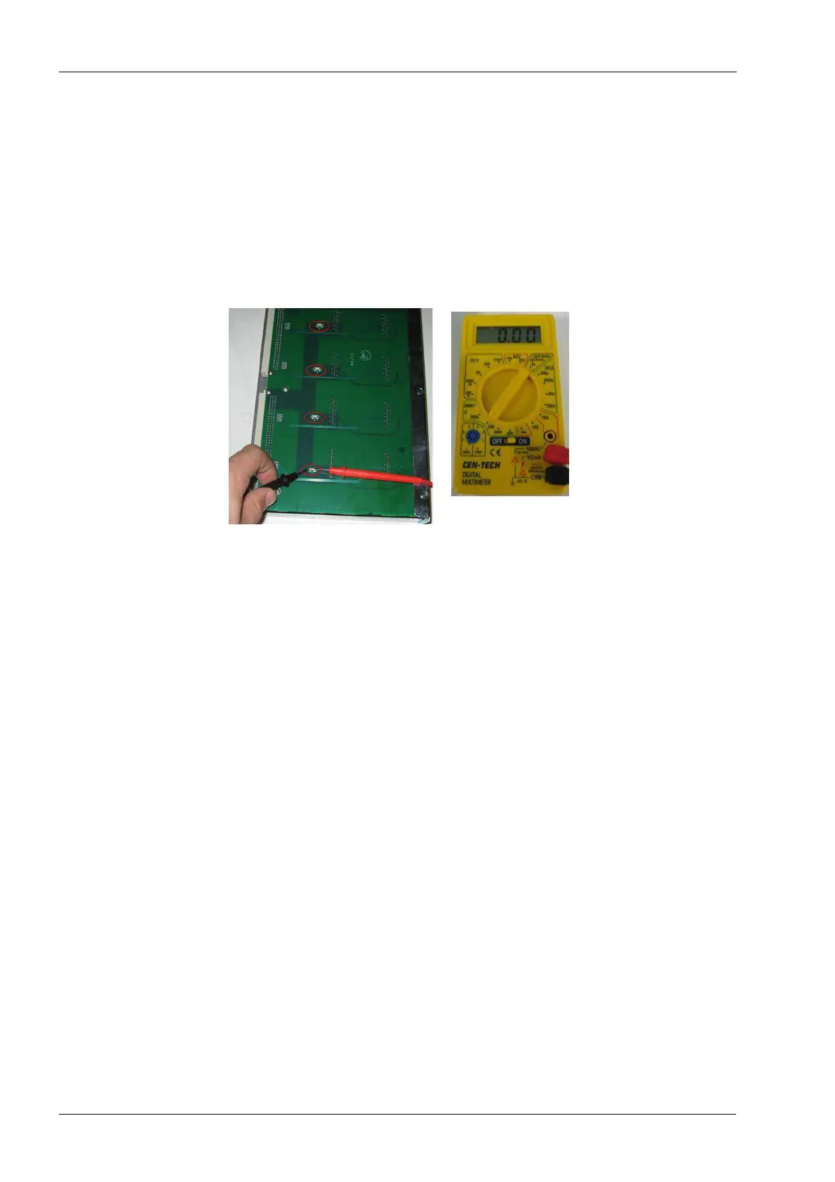
Fuse verification
There are four fuses located on the amplifier module. If one of the green LEDs fails to light
up while the circuit is closed it is necessary to check the fuses.
1. Remove the amplifier module from the upper electronics box, see above procedure.
2. Lay the amplifier module so that the fuses are facing up and check each fuse with an
ohm meter. Each fuse should read 0 ohms. A high resistance rating indicates a faulty
fuse and requires replacement of the amp module assembly.
Figure 86: Fuse verification
Install
1. Position the amplifier module in upper electronics box, carefully align the top and
bottom card slot guides.
2. Slide the amplifier module in place; it should slide freely until the edge connector
interfaces the backplane connector. At this point some resistance will be felt. Apply an
even firm force to the face of the module to seat it fully.
3. Secure the amplifier module in upper electronics box with two button head screws
using 2 mm Allen key.
Verify
1. Plug in system and press the Power button to boot the system.
2. Verify that the green LEDs are illuminated after initialization.
3. Verify system initializes and homes all assemblies with no errors.
2.2.4 Fan (electronics box exhaust)
The exhaust fan is located inside the upper electronics box. It is powered off the
backplane board and exhausts air out of the box.
Tools required
• 3 mm Allen key
• #2 Philips screwdriver
Removal
1. Power the milling unit down.