2 Basic repair procedures Chapter E: Basic repair procedures
108 Planmeca PlanMill 40 Technical manual
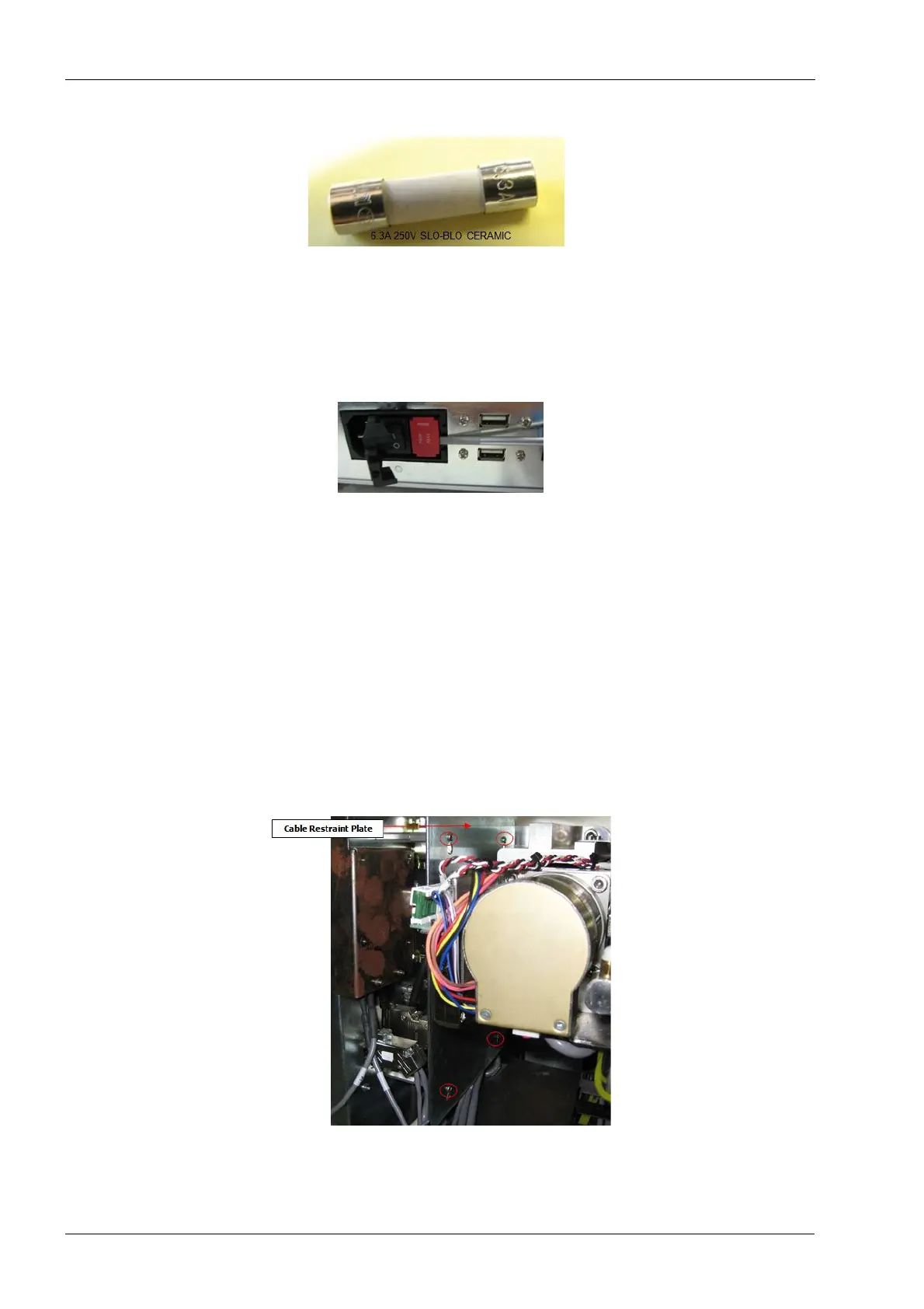
Figure 91: Fuse
3. Use the small flat screwdriver to pry the left side of the fuse holder until the holder can
be pulled back and out of the module.
Prying the top or bottom of the holder may result in damage to the fuse holder.
Figure 92: Prying fuse holder out
4. Once removed locate the fuses and remove them.
Install
1. Insert 2 new fuses (1 in each side) ensuring that fuses are properly located as shown
in the figure 89.
2. Insert the fuse holder into the power entry and snap the cover closed.
2.2.6 Cable restraint plate
All electrical connections are made on the inside face of the upper electronics box. Due to
the close proximity with the Y and Z-axis assemblies a cable restraint plate is installed to
ensure no cables can contact and become damaged by the movement of the motion base
assembly. To access any of the cables this plate must be removed.
Figure 93: Cable restraint plate