2 Basic repair procedures Chapter E: Basic repair procedures
178 Planmeca PlanMill 40 Technical manual
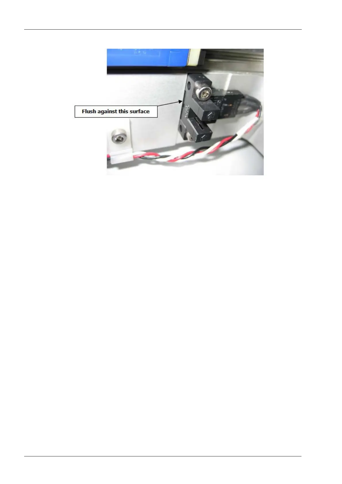
Figure 192: Installing X-axis limit sensor
2. Secure with two M3 screws.
3. Connect the limit sensor electrical connector to the interconnect board.
Verify
1. On mill screen touch Maintenance Icon.
2. Select Advanced and enter passcode 1234.
3. Select Technician Console.
4. Select High Level button.
5. Select the Mechanical Control box.
6. Select the Axis Positions box.
7. Move the X-axis inboard to its limit; verify the LED on the limit sensor goes off once
the flag has entered the sensor. Once the LED has turned off, verify the ‘L’ is
displayed to the right of the X-axis position value in the Axis Positions Box, this
indicates the limit sensor is activated.
8. Move the carriage outboard off the sensor, the LED on the sensor should illuminate
and the ‘L’ on the display should disappear.
2.13.7 Y-axis home and limit sensor
Use the same procedure for both the Home and Limit sensors.
Replacement, adjustment or disturbance of a Home Sensor or the associated flag
requires subsequent complete mill calibration.
Tools required
• 2.5 mm Allen key
• small diagonal cutters
• replacement wire ties