Chapter E: Basic repair procedures 2 Basic repair procedures
Technical manual Planmeca PlanMill 40 179
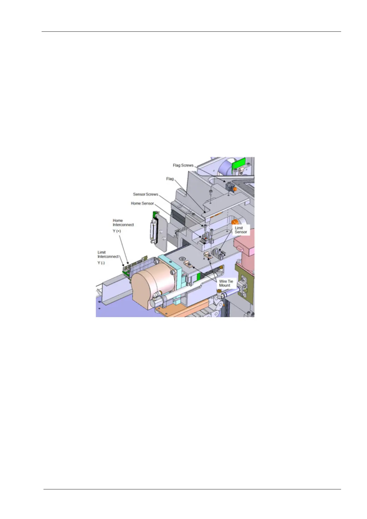
Removal
1. Remove top cover, see section 2.1 "Mill covers" on page 94.
2. Disconnect the electrical connector for the sensor from the servo interconnect board.
3. Clip the cable tie to free the cable.
4. Remove the (2) screws securing the Y-axis flag to the top of the Channel Mount base.
Lift the sheet metal flag free of the assembly.
Once the flag has been removed, all calibration procedures must be performed.
5. Remove the (2) screws securing the sensor to the Y-axis assembly. Lift the sensor
free of the assembly.
Figure 193: Removing Y-axis home sensor
Install
1. Position the new sensor on the Y-axis assembly, align the mounting holes.
2. Install the (2) mounting screws. Torque the mounting screws to 1.1 nm (10 in-lbs)
each.
3. Route the wires through the wire tie mount and secure the cable.
4. Reconnect the electrical connector to the interface board.
5. Reinstall the flag using the (2) screws removed previously. Torque the mounting
screws to 1.1 nm (10 in-lbs) each.
Make sure the cable is free from the flag during operation.
6. Power unit on and verify the mill homes this and all axes properly.
7. Perform full mill calibration procedure, see Chapter C: "Calibration" on page 49.
8. Replace top cover.