Chapter B: Preventive maintenance 2 Maintenance procedures
Technical manual Planmeca PlanMill 40 33
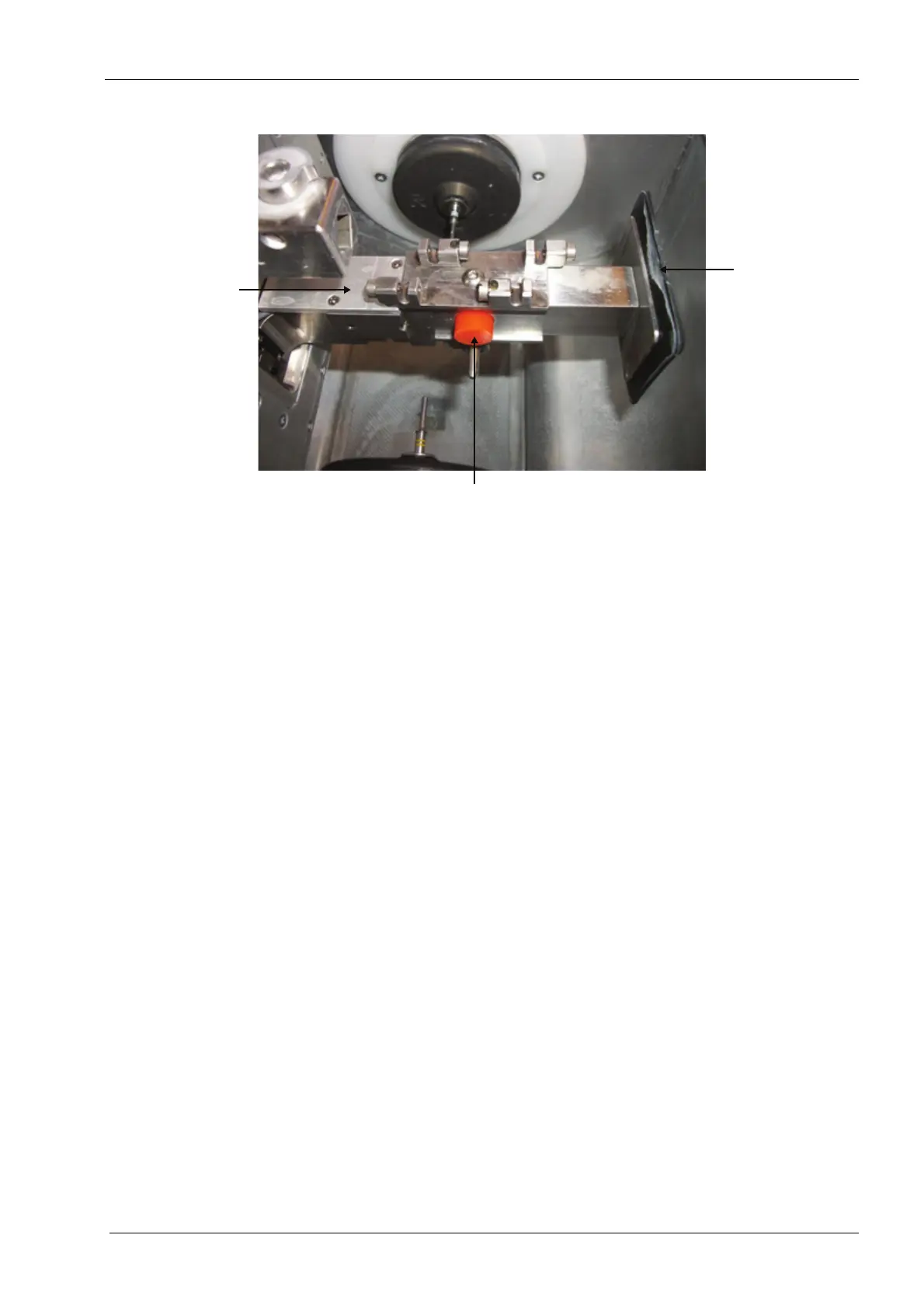
Figure 24: Inspecting tool changer 6-pack, bumper and nose seal
4. Inspect the tool changer 6-pack for any visible damage.
The mounting screw for the tool changer 6-pack should be tight and the tool changer 6-pack
should be tight against the tool changer arm. If it is not it must be corrected and the mill
must be calibrated.
5. If tools (burrs) are in the 6-pack grasp the shank of the tool and disengage it and then
insert it again in the 6-pack in the same location. The tool should snap in and out
smoothly. When in position the tool should be held firmly by the 6-pack. Do not move
it to a different position.
6. Use a spare tool to inspect the other positions in the 6-pack. Replace the 6-pack if it is
damaged, the tools do not disengage and insert smoothly or the tools are not held in
position firmly.
7. Inspect the bumper for damage or wear.
8. Inspect the nose seal for damage or wear.
2.5 Verifying correct interlock switch function
There are two micro-switches located under the upper right and left corners of the PlanMill
40 lid which detect whether the grind chamber lid is opened or closed. These switches are
safety features designed to prevent the operator from operating the spindles or the motion
system with the grind chamber lid in the open position. If interlock switch function is not
correct refer to section 2.3 "Grind chamber lid/adapter assembly" on page 117 for repair
instructions.
1. Select the Maintenance Icon in the lower left corner of the display.
2. Select Advanced and enter passcode 1234.
3. Select Technician Console.
4. Touch the High Level button.
5. Observe the box labelled Mechanical Control in the upper left corner of the display.
6. LID: CLOS CLOS should be displayed.
7. Touch the box labelled Mechanical Control in the upper left corner of the display.