Chapter E: Basic repair procedures 2 Basic repair procedures
Technical manual Planmeca PlanMill 40 153
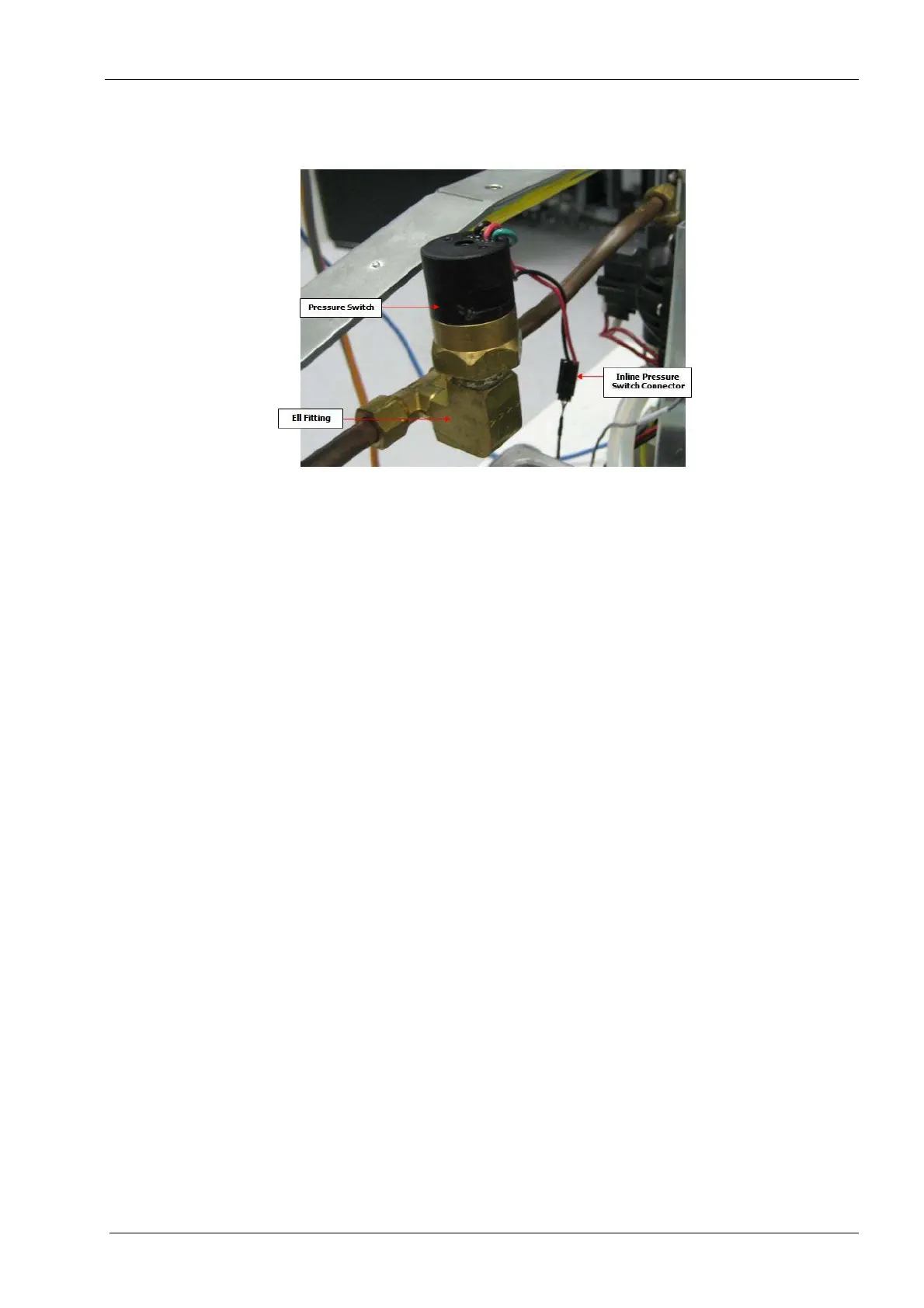
2.11.2 Water pressure switch
Figure 163: Pressure switch
Tools required
• two small crescent (adjustable) keys
• Teflon pipe tape or thread sealant
Removal
1. Remove the top cover, see section 2.1 "Mill covers" on page 94.
2. Disconnect the inline pressure switch connector.
3. Loosen the pressure switch from the ell fitting and remove.
Loosen the connection using the two keys. Use the second key to back up the
torque applied to the fitting to minimize or eliminate the stress imposed on the cop-
per tubing.
Install
1. Apply Teflon pipe tape or thread sealant to the male threads of the new pressure
switch.
Make sure no Teflon paste or tape is allowed to protrude into the wetted parts of the
connection as any debris could result in premature switch failure or prematurely
clogged nozzles from the debris.
2. Thread the Pressure switch into the 90 degree ell fitting until water tight.
Tighten the connection using the two keys Use the second key to back up the
torque applied to the fitting to minimize or eliminate the stress imposed on the cop-
per tubing.
3. Reconnect the inline connector.
4. Turn the pump on and check for leaks using the following command: Technician
Console --> High Level --> Mechanical Control --> Start Pump button.