Chapter E: Basic repair procedures 2 Basic repair procedures
Technical manual Planmeca PlanMill 40 175
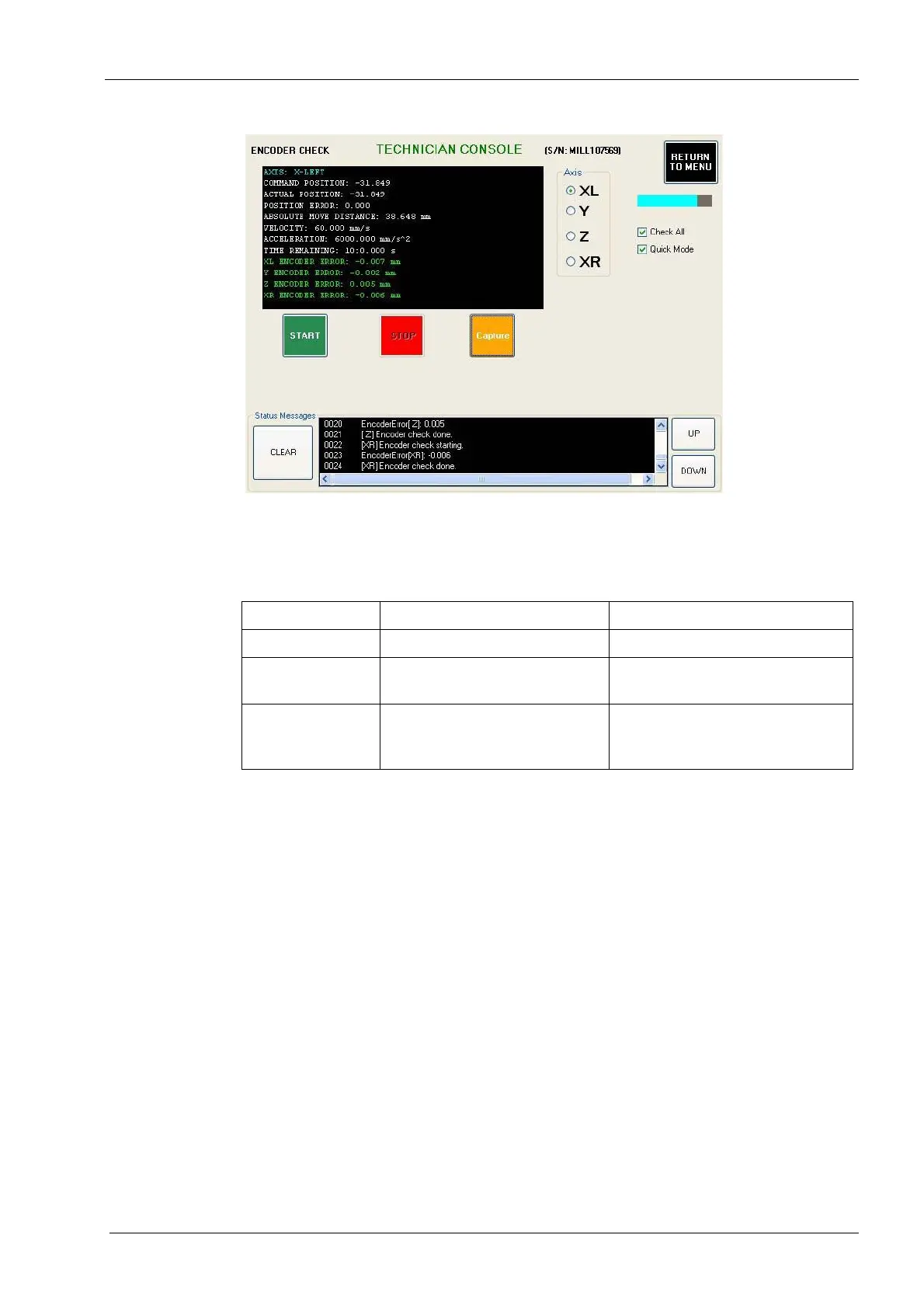
Figure 188: Encoder check
8. Select the Axis:Z. Unselect Check All. Select Quick Mode. Select the START button.
After a few minutes, the encoder error for the Z-axis will be printed in the text box in
the upper left corner of the screen. See the table below for encoder error guidelines.
Table 6:
Encoder error guidelines
2.13.4 Home and limit sensors identification
Home and limit sensors are located on each of the 4 axes. The sensors are an optical
design and are triggered by interrupting an infra-red optical beam between the two posts
of the sensor. Each axis uses a metal sensor flag mounted on the respective carriage to
trigger the sensor. The flag is positioned such that the sensor triggers approximately 1-2
mm before hard-stop end of travel for the axis. Each axis has one home sensor and one
limit sensor; the home sensors are located as follows:
• L and XR -axes are fully retracted from the origin to the outsides of the machine
• Y-axis is fully retracted from the origin to the back of the machine
• Z-axis is fully down
The limit sensors are located at the opposite end of travel on each axis and are as follows:
• L and XR -axes are fully in-board past the origin, with tools installed the tips of each
tool barely clears the nozzle cap on the opposite spindle.
• Y-axis is fully forward past the origin.
• Z-axis is fully up.
See appropriate procedure following for sensor to be replaced.
Encoder error Problem Solution
0 to 0.015 Acceptable encoder error. No action required.
0.015 to 0.100 Weak servo, defective encoder,
and/or defective cable.
Replace servo motor and retest.
Replace cable if needed.
0.100 or greater Loose motor coupling, defective
encoder, and/or defective
cable.
Tighten motor coupling and retest.
Replace servo motor and/or cable
if needed.