Chapter E: Basic repair procedures 2 Basic repair procedures
Technical manual Planmeca PlanMill 40 127
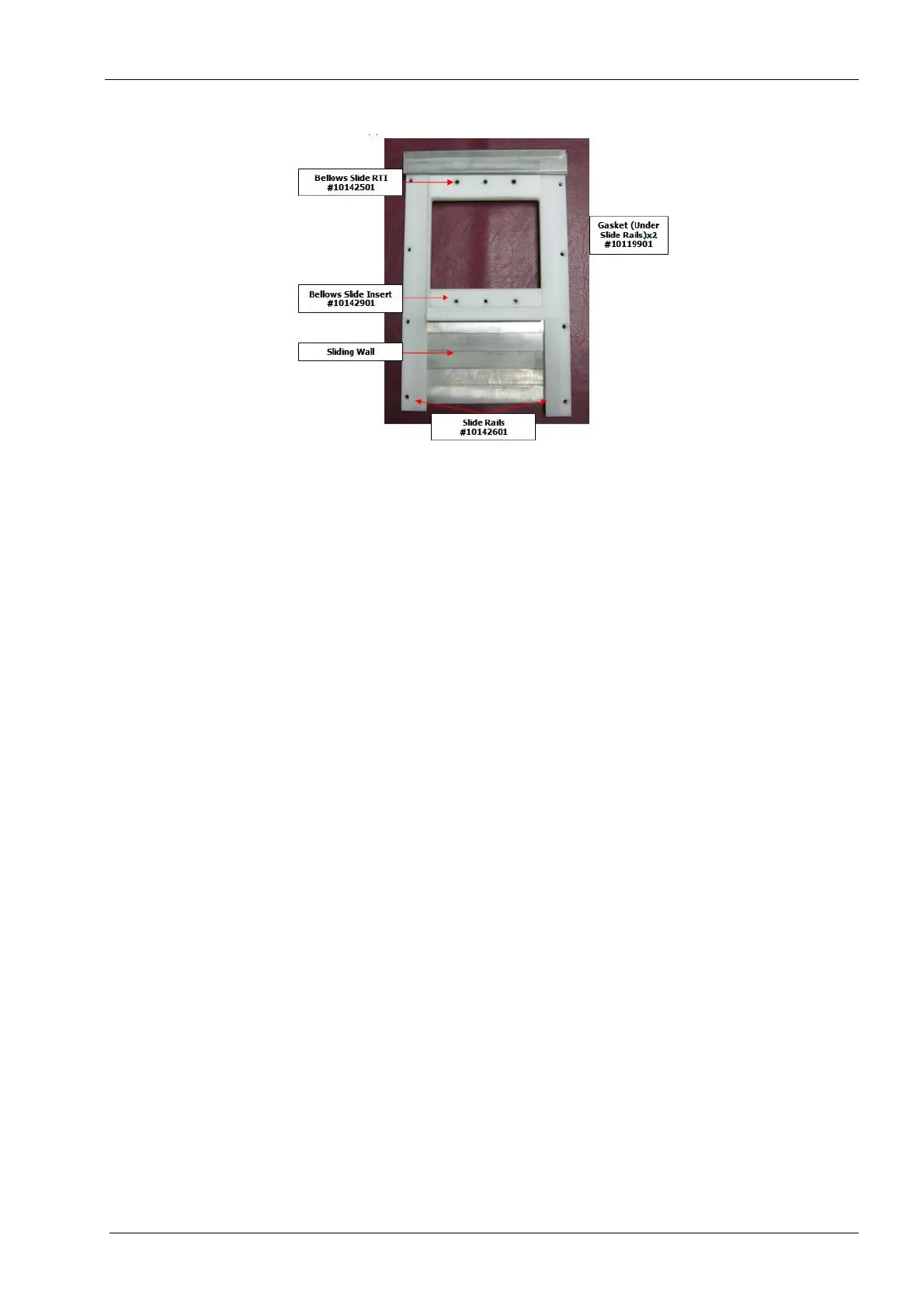
Figure 121: Sliding wall assembly
8. Slide the sliding wall and mount off of the tool changer assembly.
Install
1. Position the two slide rails on each side of the bellows slide RTI.
2. Slide the sliding wall, slide rails, and sliding wall mount together onto the tool changer
assembly.
3. Using (3) screws attach bellows slide insert to bellows slide RTI, see figure 121.
4. Use (4) screws to attach both slide rails to the grind chamber, see figure 121.
5. Use (3) screws to attach bellows flange to the bellows slide RTI, see figure 119.
6. Use (8) screws to attach tool changer assembly to bellows, see figure 118.
7. Reinstall lid adapter assembly, see section 2.3 "Grind chamber lid/adapter assembly"
on page 117.
2.4 Tool changer
The tool changer assembly can be serviced as a whole assembly or individual
components can be changed as required.
Attention!
Replacement of a tool changer assembly requires subsequent completion of tool
changer calibration, tool profiler calibration and origin calibration procedures.
Proper installation of these components is critical to the overall performance and operation
of the milling unit.
The following procedure is to remove and reinstall the entire tool changer assembly.