2 Basic repair procedures Chapter E: Basic repair procedures
128 Planmeca PlanMill 40 Technical manual
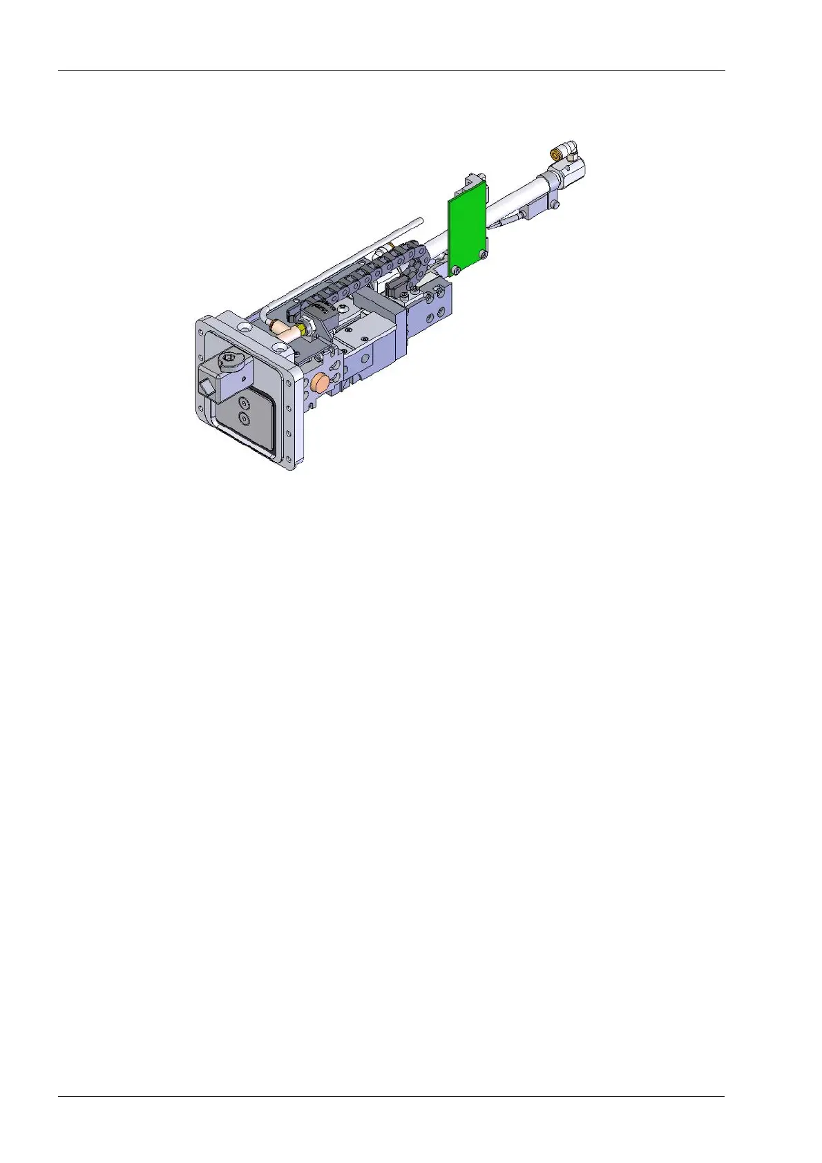
Figure 122: Tool changer assembly
Tools required
• metric Allen key set
• 4 mm Allen key stubby style
• #0 Philips screwdriver
• small flat screwdriver
• 1 wooden shipping block
• Loctite 565 Thread Sealant or similar
• needle nose pliers
Removal
1. Use Advanced (enter code 1234), Verify Tools to remove any tools in the collets or
the tool holder (Replace Tools will be used to reload tools after calibration is
completed).
2. Remove the top cover, left side panel and rear covers, see section 2.1 "Mill covers" on
page 94.
3. Open the grind chamber lid.
4. Manually raise the Z-axis to the top of its travel. When raising the Z-axis, make sure
not lift from the fragile parts i.e. servo, encoder etc.
5. Place a wooden shipping block under the tool changer chassis and the lower E-box.
Lower the Z-axis smoothly on the top of the wooden block. The block should leave the
Z-axis elevated to ease the tool changer removal.