Chapter E: Basic repair procedures 2 Basic repair procedures
Technical manual Planmeca PlanMill 40 129
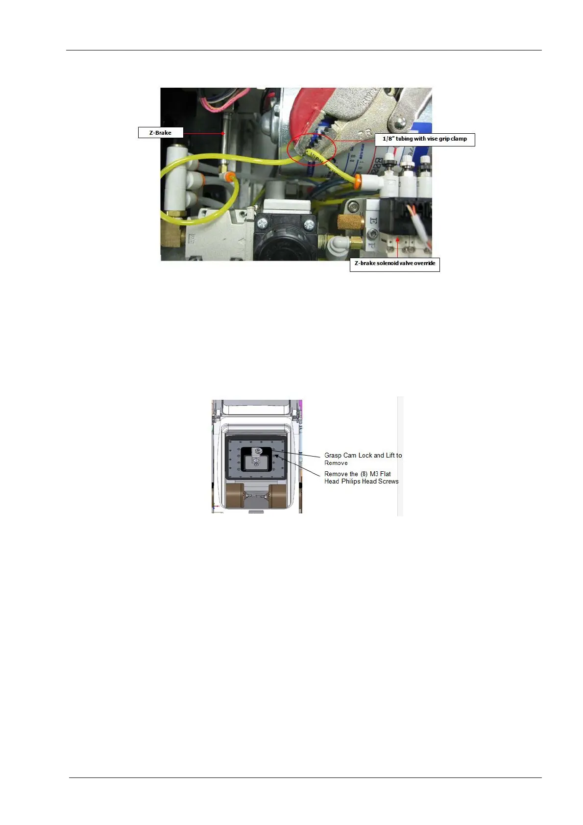
Figure 123: Activating Z-brake and using clamp on tubing to keep it on
Removing grinders from collets may allow easier access to screws; remember to install 4
mm dowel pins into the collets so the collets are not closed empty, which could damage
them.
6. Remove the cam lock from the mandrel holder.
7. Remove the remaining (8) M3 flat head Philips screws from the bellows flange.
Figure 124: Removing bellows flange