2 Basic repair procedures Chapter E: Basic repair procedures
130 Planmeca PlanMill 40 Technical manual
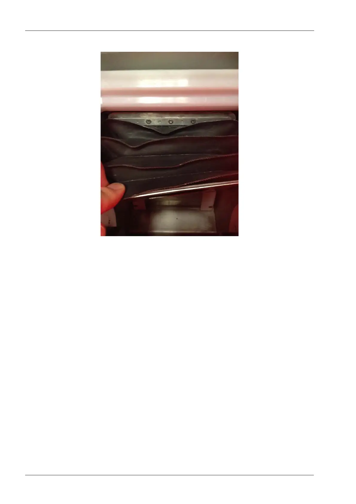
Figure 125: Remove the (3) M3 Philips flat head screws
8. Carefully grasp the front flange of the bellows and lift it over the stop pin for the cam
lock on the mandrel holder. Then pull the flange forward exposing the (3) M3 Philips
flat head screws securing the rear flange of the bellows assembly to the sliding wall
assembly.