2 Basic repair procedures Chapter E: Basic repair procedures
94 Planmeca PlanMill 40 Technical manual
2 Basic repair procedures
2.1 Mill covers
Most service operation will require removal of one or more of the covers enclosing the
milling unit. In many cases this is limited to simply removing the top cover and possibly
one of the side covers while leaving the other covers in place. This also has the advantage
of allowing most service items to be addressed from the front (top) and sides of the
machine thus minimizing the requirement to disconnect the rear connections and
reposition the milling unit.
If the mill is operational and has pneumatic power sufficient to unlock the drawer and open
the grind chamber then the top cover and subsequently the side covers can be removed
without removing the rear cover. However, if the mill is not operational or sufficient air
pressure is not available then the rear cover should be removed first. Once the rear cover
is removed the drawer lock assembly may be raised manually to allow opening of the
drawer and access to remove of the top cover.
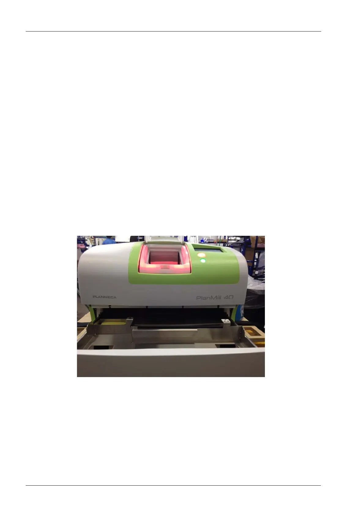
2.1.1 Top cover
Tools required
• metric Allen key set
Figure 71: PlanMill 40 top cover assembly
Removal
1. Select Advanced, enter code 1234, select Technician Console, select High Level,
select Mechanical Control.
2. Touch the Unlock Drawer button.
3. Touch the Open Lid button.
4. Locate and loosen the four front screws securing top cover to the frame, it is not
necessary to completely remove the screws.