Chapter E: Basic repair procedures 2 Basic repair procedures
Technical manual Planmeca PlanMill 40 95
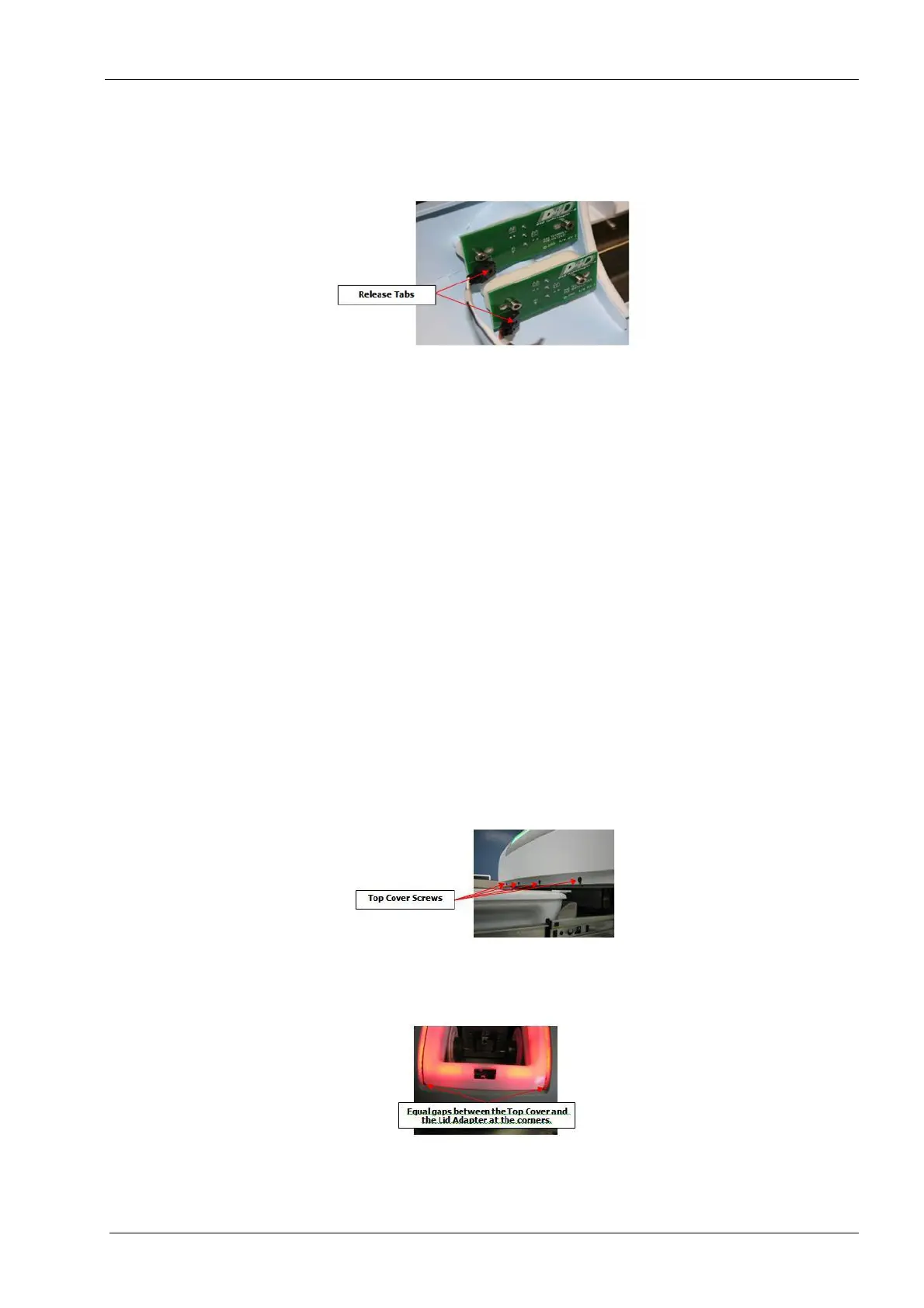
5. Carefully lift the front of the top cover approximately 12.5 cm and disconnect the stop
switch cable (3 pin connector) and On/Off switch cable (4 pin connector) connectors
by depressing the plastic release on the connectors.
Figure 72: Disconnect switch cables
Use care lifting top cover off PlanMill 40 to avoid damaging the wiring to the stop
switch and on/off switch.
6. Once the cables are disconnected, raise the top cover up and lift off the machine.
Install
1. Select Advanced (enter code), Technician Console, High Level, Mechanical Control.
2. Touch the Unlock Drawer button.
3. Touch the Open Lid button.
4. Ensure both side covers are installed.
5. Align the top cover between the two side covers; position the flange on the rear of the
top cover under the rear cover. Rotate the top cover down to allow reconnection of the
stop and power switches.
6. Connect stop switch cable and on/off switch cable.
7. Lower the top cover in place ensuring the sides align properly with left and right
covers, and the opening is properly aligned with the grind chamber.
8. Install, but do not tighten the four front screws and washers securing the top cover to
the chassis.
Figure 73: Top cover screws
9. Recheck the top cover alignment per the following figures, and then tighten the four
front screws.
Figure 74: Fit to lid and lid adapter