Chapter E: Basic repair procedures 2 Basic repair procedures
Technical manual Planmeca PlanMill 40 165
2.13 Motion base assembly repair
Figure 175: PlanMill 40 motion base assembly
2.13.1 X-axis servo motor and coupling
The following procedure applies to replacing either the right or left X-axis servo motor. The
procedure is the same for both left and right axes except where noted. Use this procedure
for replacing either the servo motor or the servo coupling.
Tools required
• 2.5 mm and 4 mm T-handle Allen keys
• 7 mm Allen key
Removal
1. Remove top cover and left and/or right side panels as required, see section 2.1 "Mill
covers" on page 94.
2. Power down the milling machine and disconnect AC power source.
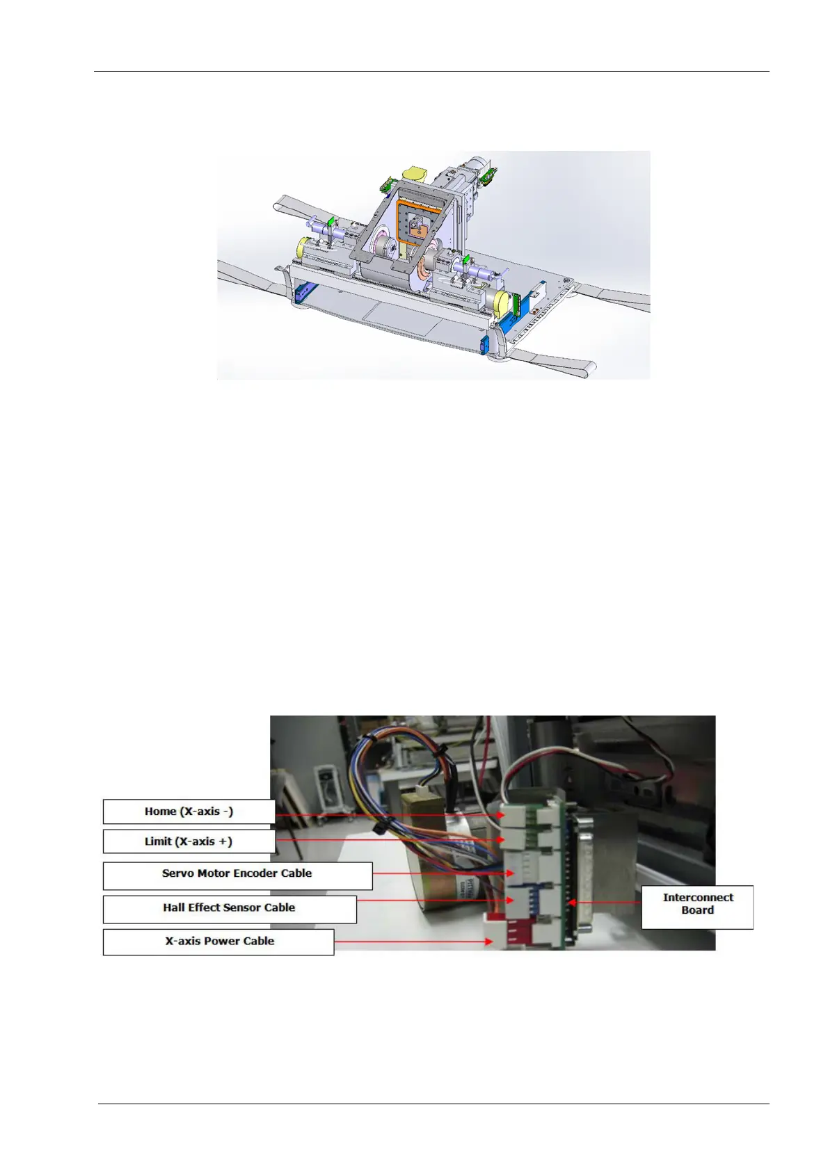
Figure 176: X-axis servo motor, home and limit sensor connections to interconnect board
To remove the servo motor on the right side it is necessary to remove the display first.
3. Disconnect X-axis servo motor power cable from the interconnect board.
4. Disconnect servo motor hall-effect sensor cable from the interconnect board.