2 Basic repair procedures Chapter E: Basic repair procedures
166 Planmeca PlanMill 40 Technical manual
5. Disconnect servo motor encoder cable from the interconnect board.
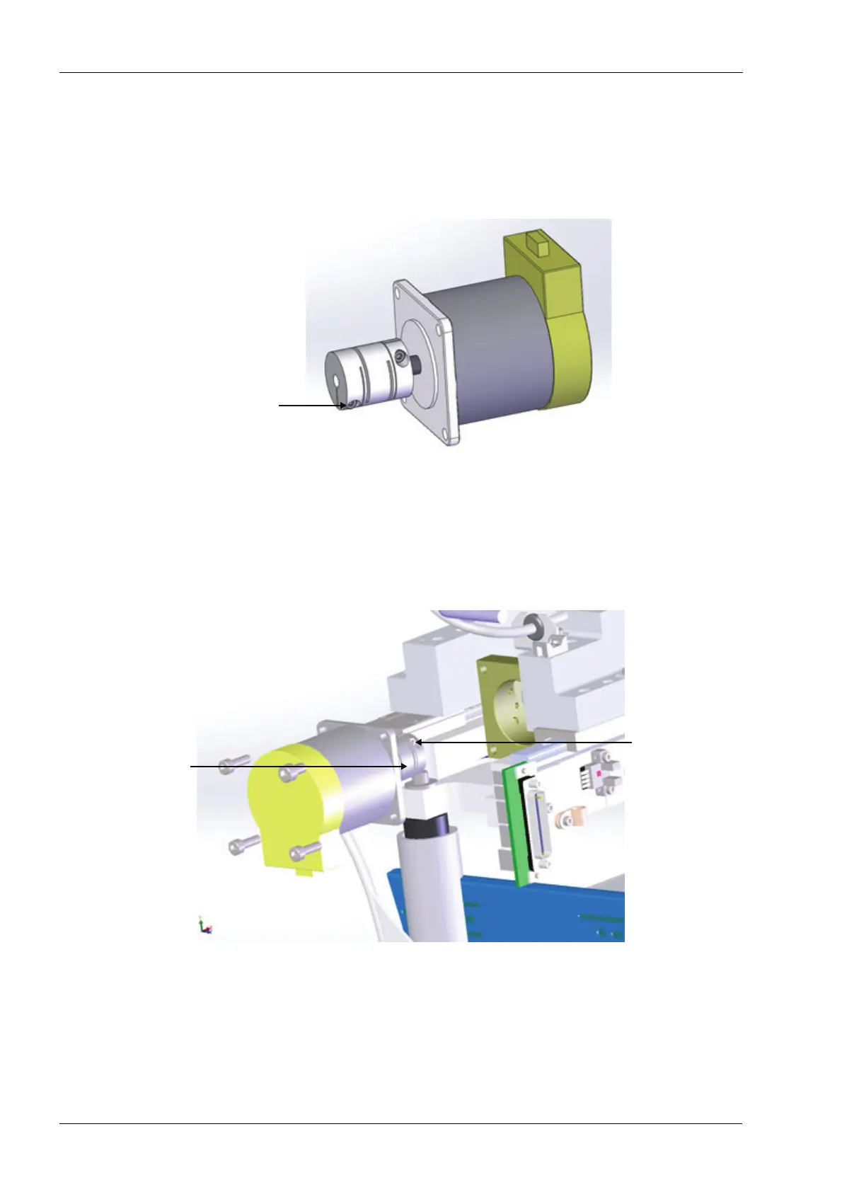
6. Loosen but do not remove the clamp screw for the ball screw end of the coupling (with
the power off and cables disconnected the coupling may be slightly rotated manually
using a pencil eraser in order to access the clamp screw). Refer to the following
figure.
Figure 177: Servo motor with coupling
Attempting to remove motor with coupling still attached to the ball screw will break
or damage the coupling.
7. Use a 4 mm Allen key and remove (4) screws securing the servo motor to the motor
mount and carefully slide the motor out of chassis. Refer to the following figure.
Figure 178: Servo motor with coupling
Install
Installation of a new servo motor requires a careful alignment procedure, described
in the following steps. Failure to follow the alignment procedure can cause prema-
ture failure of mill components.
Clamp screw for
ballscrew
end of coupling
Servo motor
coupling
Loosen clamp
screw on the
ballscrew
end of coupling