Chapter E: Basic repair procedures 2 Basic repair procedures
Technical manual Planmeca PlanMill 40 109
Tools required
• metric Allen key set
• #1 Philips screwdriver
Removal
1. Remove the top and rear covers.
2. Loosen but do not remove the upper (2) retaining screws securing the restraint plate.
You may need to use a small adjustable key or pliers to restrain the standoff from rotating
while you loosen the screws.
3. Manually raise the Z-axis assembly to allow access to the lower (2) screws.
4. Slide the plate up approximately 5 mm and remove the plate through the keyholes.
Install
1. Align the plate over the keyholes and slide down onto the (4) screws.
2. Secure the (2) upper screws.
3. Raise the Z-axis to access the (2) lower screws and secure.
4. Reinstall the top and rear covers.
2.2.7 LCD touch display assembly
This assembly includes a 4” diagonal, 640 x 480 LCD display with touch screen overlay,
processor boards, sheet metal enclosure and plastic bezel. This assembly should be
replaced as a unit and the original returned to Planmeca After Sales for refurbishment.
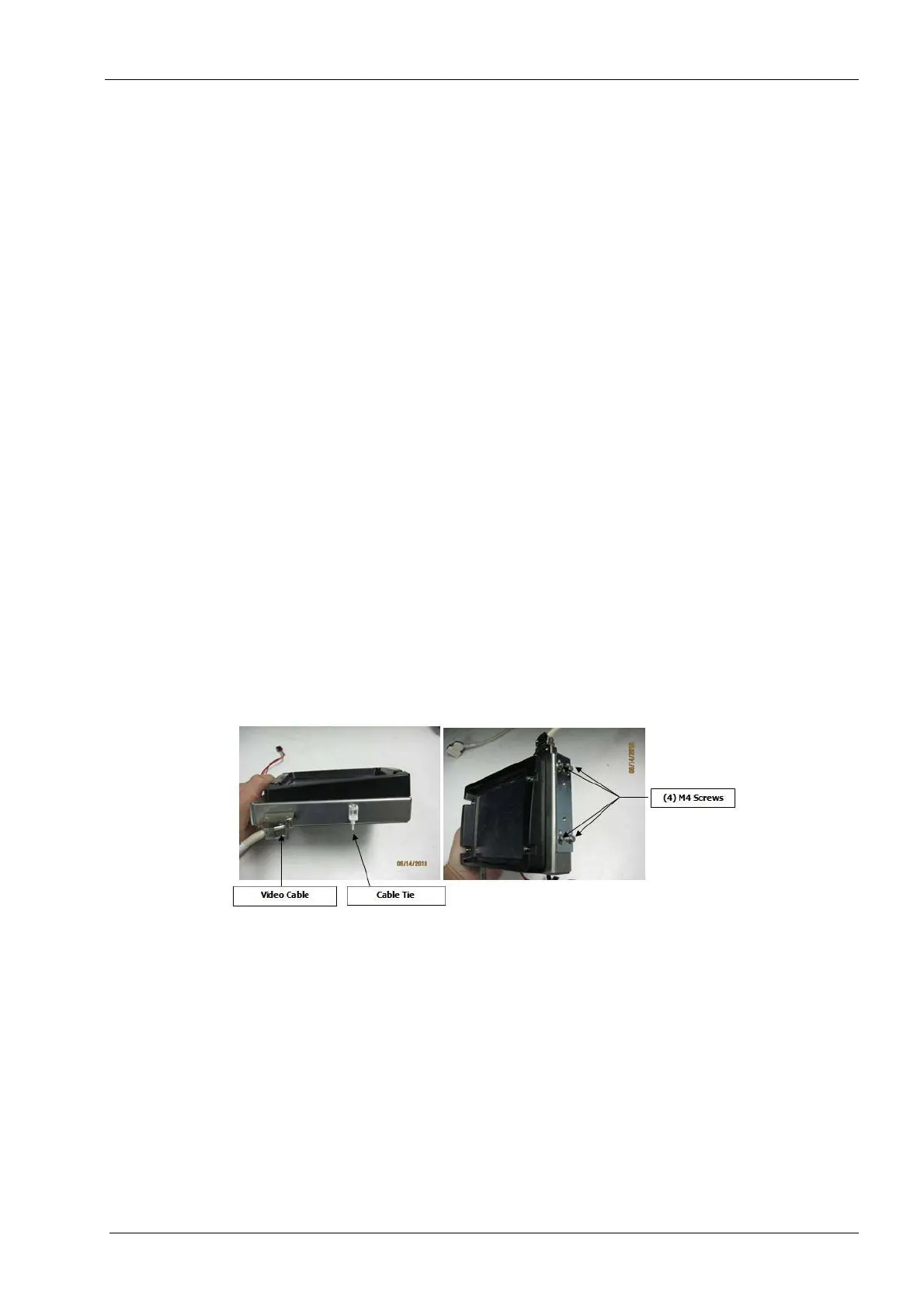
Figure 94: Touchscreen display
Tools required
• 2.5 mm and 3 mm Allen keys
• wire cutters
• small zip tie
Components of the LCD touch screen assembly can be damaged by electrostatic
discharge. Be sure to ground yourself properly before handling these components.
Removal
1. Remove top and right side covers, see section 2.1 "Mill covers" on page 94.