Chapter E: Basic repair procedures 2 Basic repair procedures
Technical manual Planmeca PlanMill 40 103
2. Depending on the units software version it may or may not automatically start the
PlanMill 40 application. If the unit does not automatically start the PlanMill 40
application, simply double tap the PlanMill 40 MillingCenter icon on the touch screen
to start the application.
3. View settings to ensure software version, IP addresses are correct.
4. Refresh license.
5. Unless the previous calibration file was able to be retained you must perform a
complete 3 stage calibration process, refer to Chapter C: "Calibration" on page 49.
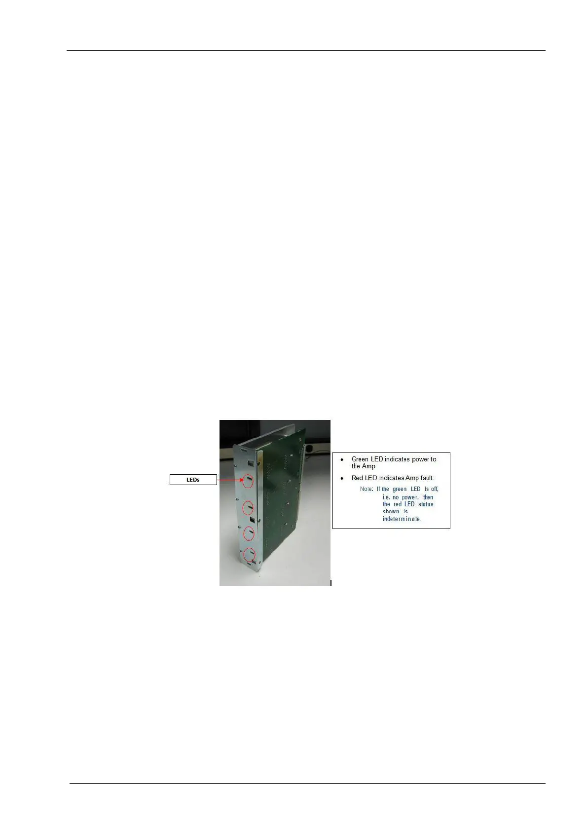
2.2.3 Amplifier module
The amplifier module is located in the upper electronics box and is mounted to the
interface board. The amplifier module has 4 red/green LEDs on its face. The green lights
indicate power to the amplifier module and should all be lit when the amplifier is
functioning properly. If one or more of these lights is off see the fuse checking procedure
at the end of this section.
Tools required
• metric Allen key set
• ohm meter
Components of the amplifier module can be damaged by electrostatic discharge. Be
sure to ground yourself properly before handling these components.
Figure 85: Amplifier module
Removal
1. Remove the top cover and right side panel, see section 2.1 "Mill covers" on page 94.
2. Power the milling unit down.
3. Remove the two button head screws securing amplifier module to chassis (one top
and one on bottom) using a 2 mm Allen key.
4. Grab top and bottom edges of amplifier module and slide module out of upper
electronics box.