Chapter E: Basic repair procedures 2 Basic repair procedures
Technical manual Planmeca PlanMill 40 195
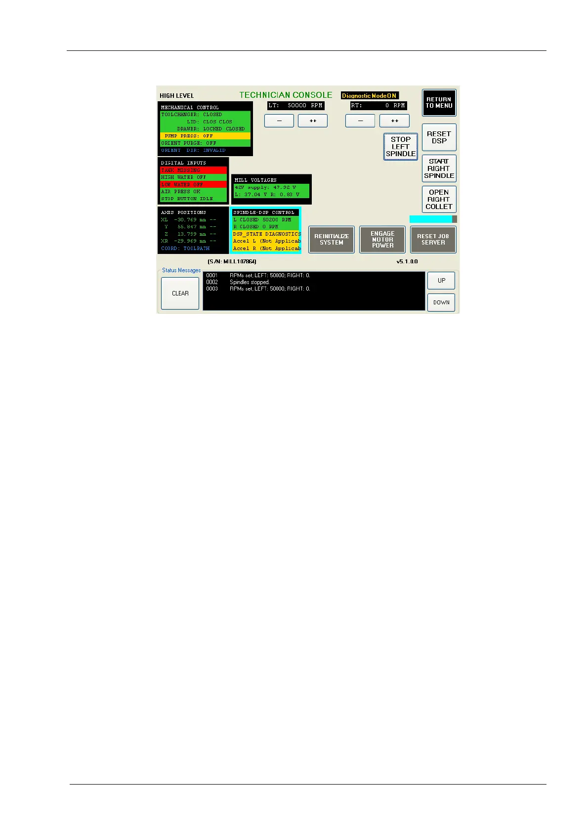
Figure 217: Verifying the RPM
9. After a few seconds, observe the RPM reading for the L or R spindle shown inside the
SPINDLE-DSP CONTROL box.
10. The RPM should be 50000 or greater.
If RPM is less than 50000 consult the spindle section troubleshooting table in chapter 3.
2.13.10 Spindle housing
The spindle housings support the spindles and are mounted to X-axis carriages. The lower
portion of the teardrop shape provides a path for coolant delivery from the rear of the
spindle to the nozzle caps. The procedure to replace the housing is the same for both left
and right spindles except where noted.
Removal of spindle requires subsequent completion of the mill calibration procedure.
Tools required
• 7 mm open end key
• two 22 mm flat open end keys
• metric Allen key set
• 3.175 mm (1/8”) pin key
Removal
1. Remove the burrs from the collets.
2. Remove the 2 spindle housing securing screws from the carriage.