2 Basic repair procedures Chapter E: Basic repair procedures
194 Planmeca PlanMill 40 Technical manual
21. Reconnect the cable retaining plate, see section 2.2.6 "Cable restraint plate" on page
108.
22. Power the mill on.
23. Perform full calibration for the mill, see Chapter C: "Calibration" on page 49.
24. Shutdown the mill.
25. Reinstall rear, side panel and top cover, see section 2.1 "Mill covers" on page 94.
Removal of spindle requires subsequent completion of the mill calibration procedure.
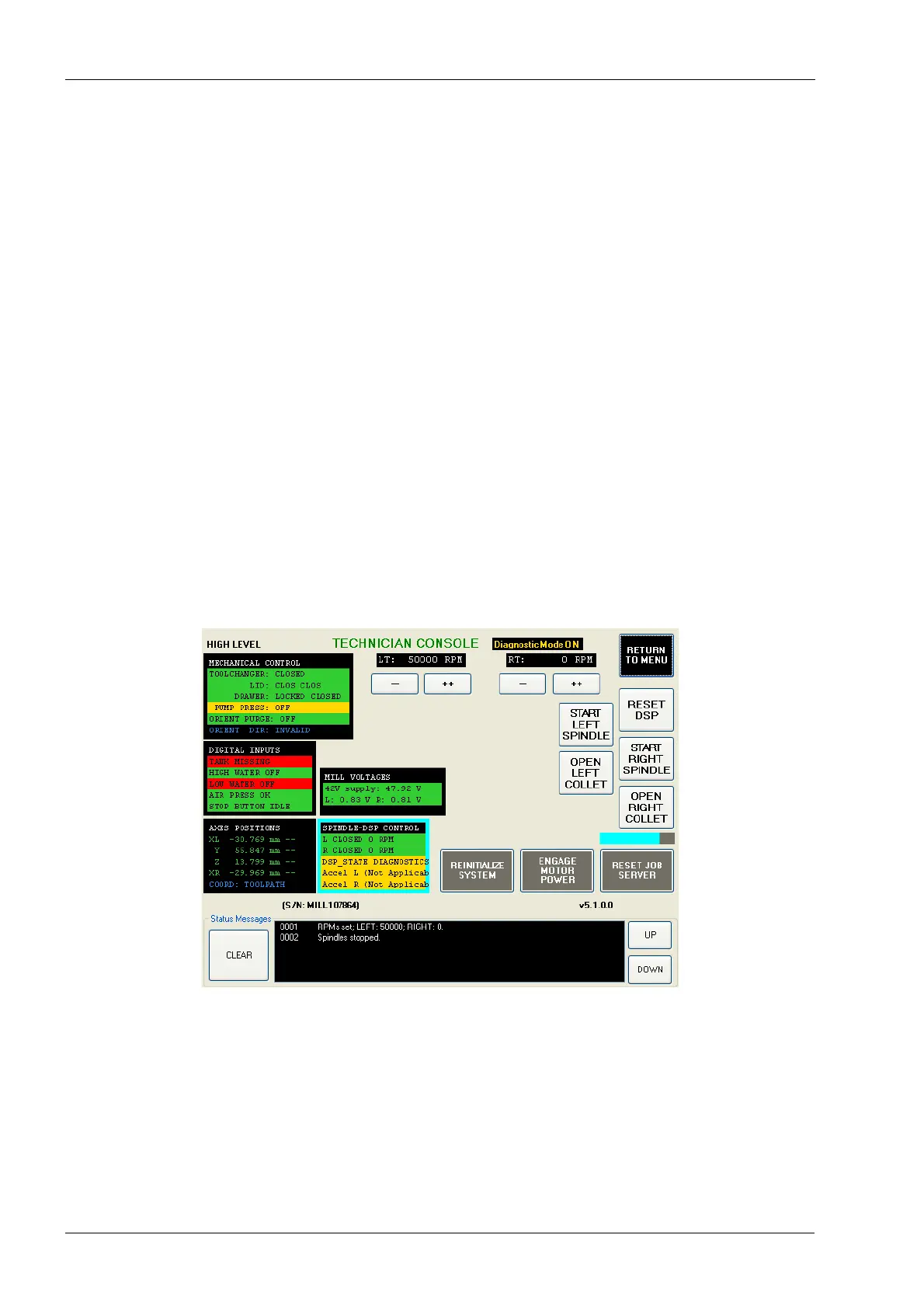
Verification
1. Power the mill on.
2. On mill screen touch Maintenance Icon.
3. Select Advanced and enter passcode 1234.
4. Select Technician Console then select High Level button.
5. Touch SPINDLE-DSP CONTROL.
6. Touch ENABLE DIAG MODE.
7. Touch START LEFT SPINDLE or START RIGHT SPINDLE according to which side
was replaced.
8. Touch the ++ button under LT or RT according to which side was replaced until 50000
is displayed as the RPM.
Figure 216: Starting the spindle