Chapter E: Basic repair procedures 2 Basic repair procedures
Technical manual Planmeca PlanMill 40 193
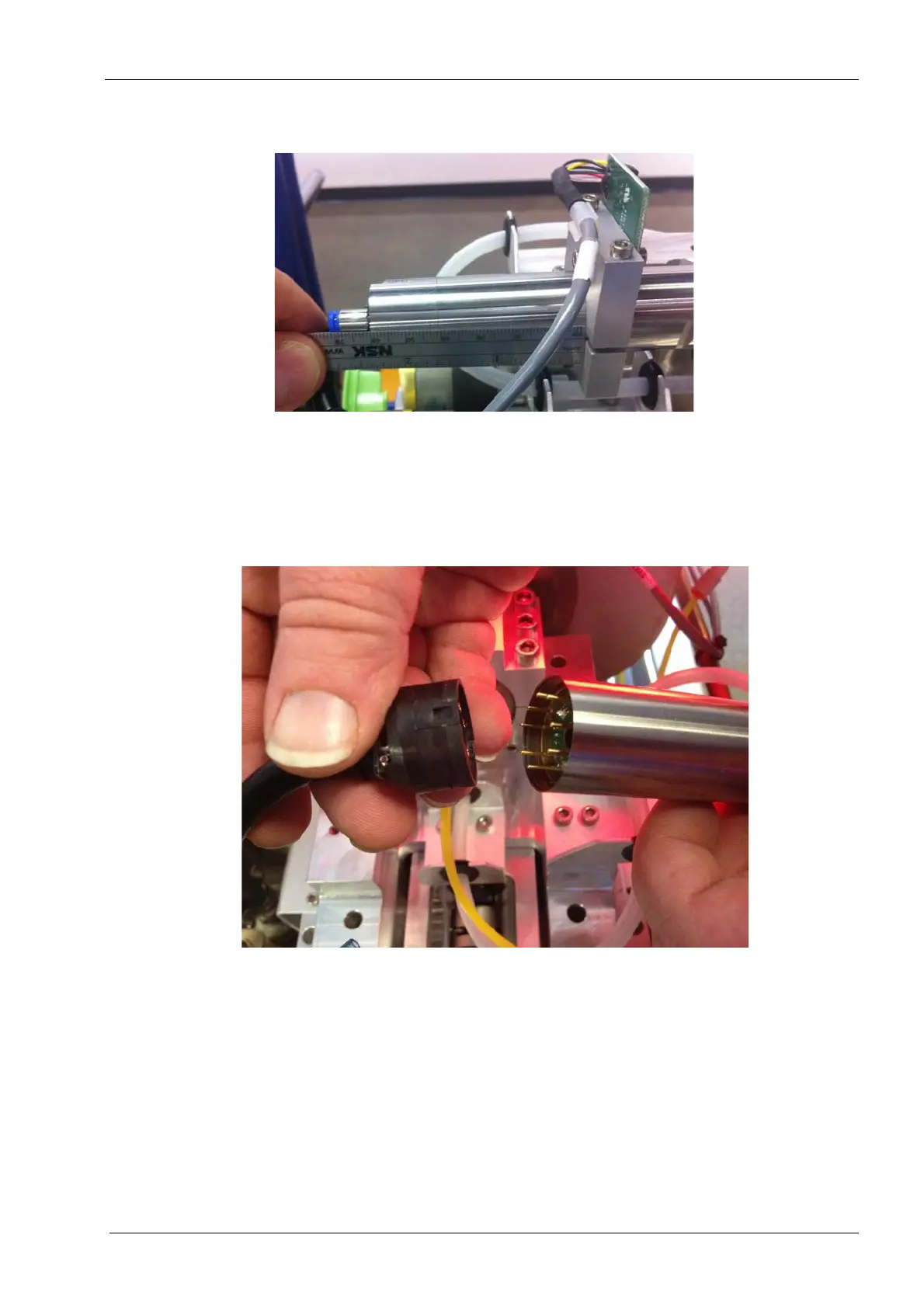
• Locate the sensor bracket is 62 mm from the end of the motor to the surface of
the bracket, see the figure below.
14. Tighten the 2 M3 screws evenly making sure the assembly is level. Torque the screws
to 1.12 nm (10 in-lbs).
Do not over tighten the accelerometer as it can damage the motor.
Figure 215: Connect spindle motor cable to spindle motor
15. Carefully connect the spindle motor cable to the spindle motor.
16. Slide the metal sleeve over the connector and carefully thread it into the spindle
motor.
17. Use the 22 mm flat open end key to snug the sleeve to the spindle motor.
Be careful to not cross thread the motor cable cap to the motor as the threads are very fine.
18. Attach blue tubing to one touch fitting on the spindle motor cap.
19. Route the spindle motor cable securing to the frame where appropriate.
20. Reconnect the spindle motor connector to the electronics box secure with (2)
retaining screws.