2 Basic repair procedures Chapter E: Basic repair procedures
174 Planmeca PlanMill 40 Technical manual
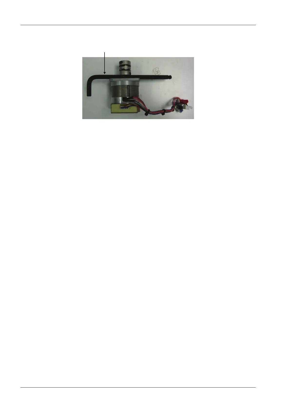
Figure 208: Setting coupling spacing
3. Install the servo motor and coupling onto the motor mount and ball screw and snug
the (4) mounting screws attaching the servo to the motor mount.
4. Snug the coupling clamp screw (on ball screw end of the coupling).
5. Loosen the (4) mounting screws on servo to allow the motor to center on the shaft.
6. Retighten the (4) mounting screws to 2.03 nm (18 in-lbs).
7. Loosen the coupling clamp screw (on ball screw end), this allows the coupling to
relieve any axial stress and re-torque to 2.03 nm (18 in-lbs).
8. Connect servo motor encoder, hall-effect and power cables to the interconnect board.
Both the hall-effect and encoder connectors are 5-pin connectors; the hall-effect
(blue connector with 5 wires) goes in the middle. Inserting the connectors wrong
can cause severe damage to the motor or amplifier.
Verify
1. On mill screen touch Maintenance Icon.
2. Select Advanced and enter passcode 1234.
3. Select Technician Console.
4. Select High Level button.
5. Select the Axis Positions box.
6. Move the Z-axis up and down to its limits; verify free non-binding operation for full
travel.
7. Navigate to: Technician Console --> Motion Diagnostics --> Encoder Check.
7 mm Allen key
used as spacer