Chapter E: Basic repair procedures 2 Basic repair procedures
Technical manual Planmeca PlanMill 40 173
Attempting to remove motor with coupling attached will break or damage coupling.
8. Use a 4 mm Allen key and remove (4) screws securing the servo motor to the motor
mount and carefully lift the motor up out of chassis.
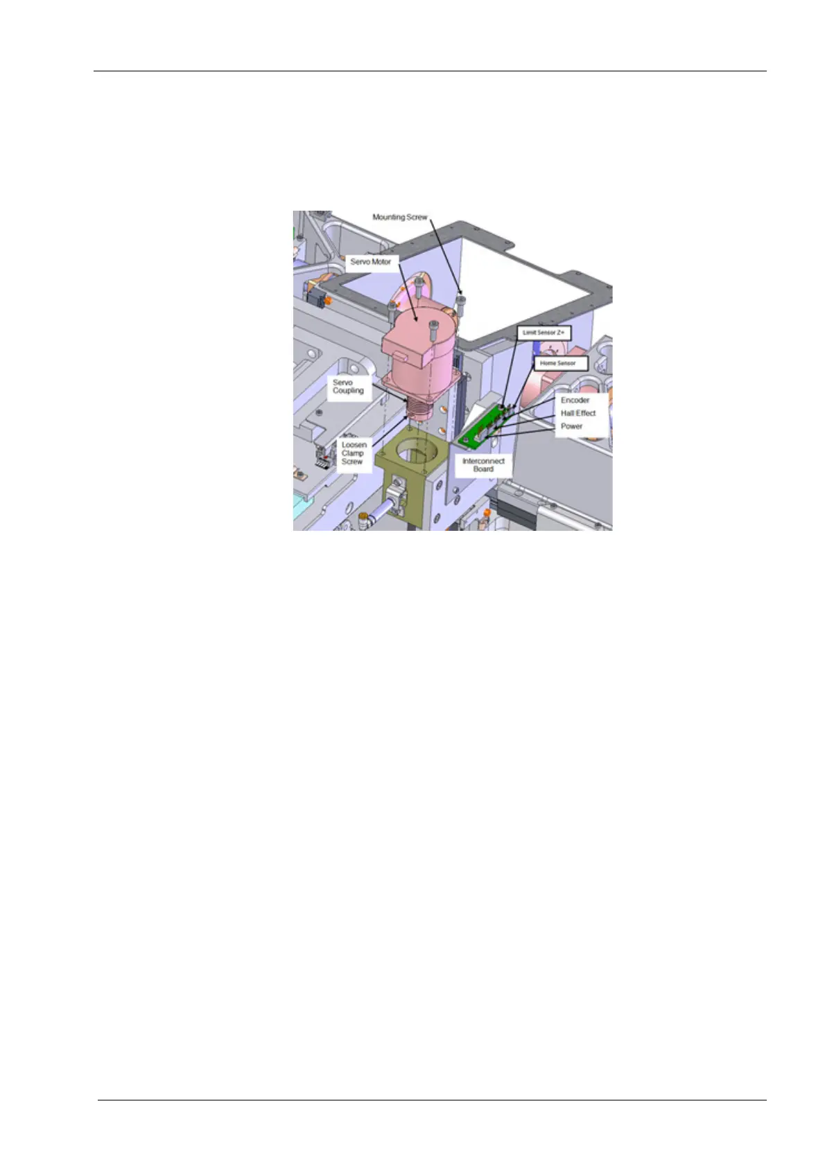
Figure 187: Removing Z-axis servo motor with coupling
Install
Installation of a new servo motor requires a careful alignment procedure, described
in the following steps. Failure to follow the alignment procedure can cause prema-
ture failure of mill components.
1. If not already installed, install the servo coupling on servo motor shaft.
The proper distance between the motor face and the servo coupling is 7 mm.
2. Torque to 2.03 nm (18 in-lbs).
Use a 7 mm Allen key as a spacer to set coupling motor shaft.