Chapter E: Basic repair procedures 2 Basic repair procedures
Technical manual Planmeca PlanMill 40 107
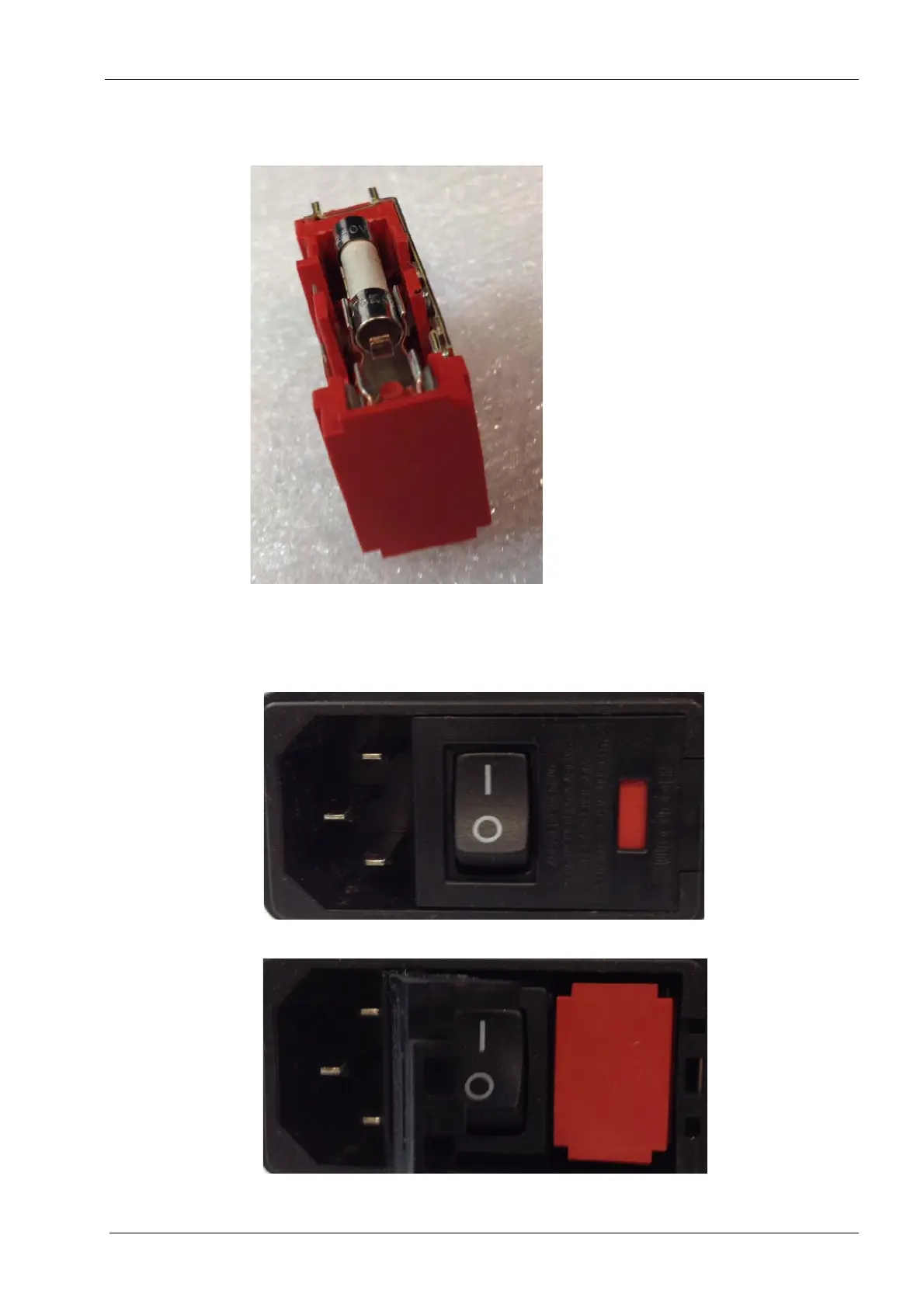
Removal
Figure 89: Fuse holder
1. Power down and unplug milling unit from AC power.
2. Locate power entry module, using a small flat screwdriver pry open the left side of the
power entry cover, it hinges on the left.
Figure 90: Power entry module
Power entry module opened