Chapter E: Basic repair procedures 2 Basic repair procedures
Technical manual Planmeca PlanMill 40 105
2. Remove the top cover, right side panel, and rear cover, see section 2.1 "Mill covers"
on page 94.
3. Remove the amplifier, CPU, and power supply modules from the upper electronics
box assembly, see section 2.2 "Electronics box" on page 99.
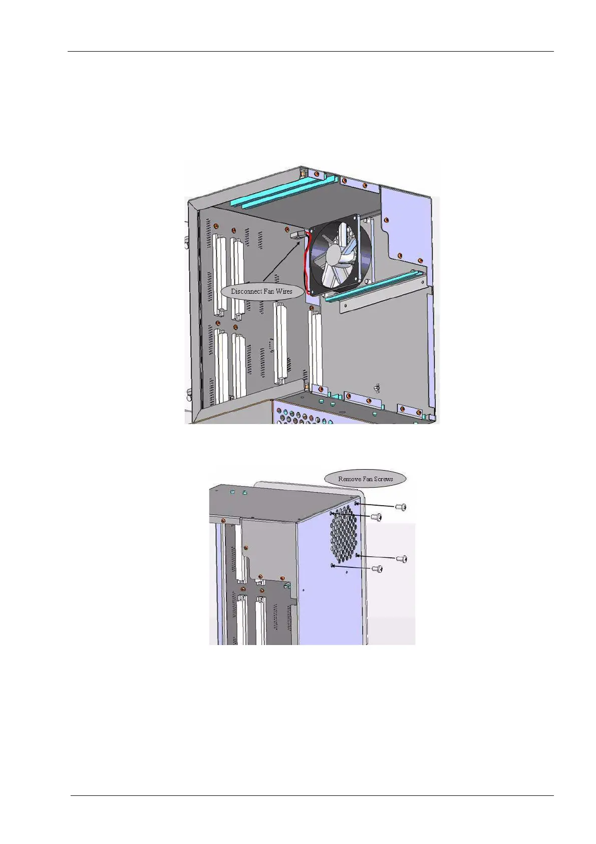
4. Inside the box locate and unplug the 80 mm fan assembly from the backplane.
Figure 87: Upper E-box fan
5. Remove the four thread-forming screws, which secure the fan assembly.
Figure 88: Fan screws
6. Remove fan from upper e-box assembly.
The accelerometer processor board is secured by the two outer screws. Gently set this
assembly aside.