Chapter E: Basic repair procedures 2 Basic repair procedures
Technical manual Planmeca PlanMill 40 181
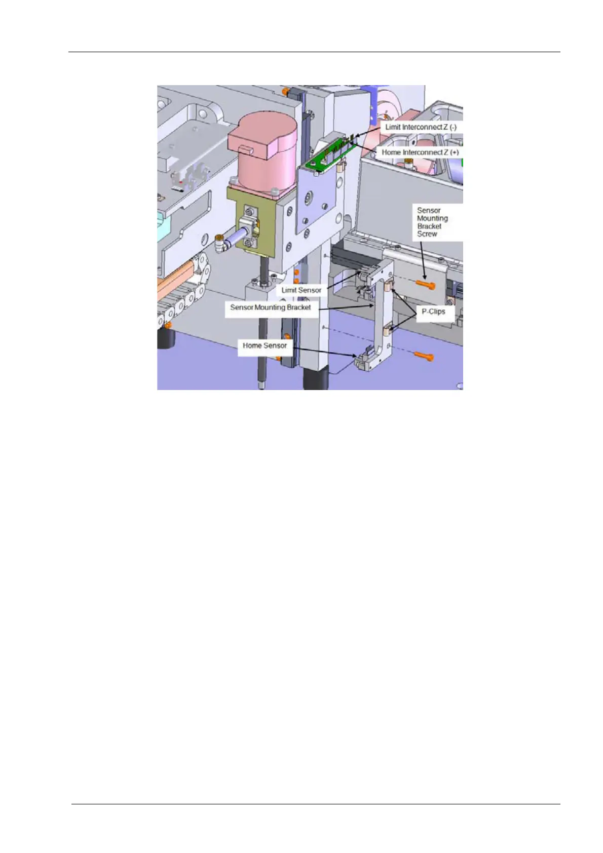
Figure 194: Removing the Z-axis home and/or limit sensor
Install
1. Position the new sensor on the Z-axis assembly, align the mounting holes.
2. Install the (2) mounting screws. Torque to 1.1 nm (10 in-lbs) each.
3. Route the cable through the p-clip.
4. Remount the sensor bracket assembly to the Z-axis rail mount plate. It may be
necessary to remove the drawer in order to reach the bottom screw. Torque screws to
2.6 nm (23 in-lbs) each.
5. Reconnect the electrical connector to the interface board.
Make sure the cable is free from the flag during operation.
6. Power unit on and verify the mill homes this and all axes properly.
7. Perform the mill calibration procedure, see Chapter C: "Calibration" on page 49.
Verify
1. On mill screen touch Maintenance Icon.
2. Select Advanced and enter passcode 1234.
3. Select Technician Console.
4. Select High Level button.
5. Select the Mechanical Control box.
6. Select the Axis Positions box.
7. If the home sensor was replaced. Verify axis homes properly.
8. If the limit sensor was replaced: