Chapter E: Basic repair procedures 2 Basic repair procedures
Technical manual Planmeca PlanMill 40 169
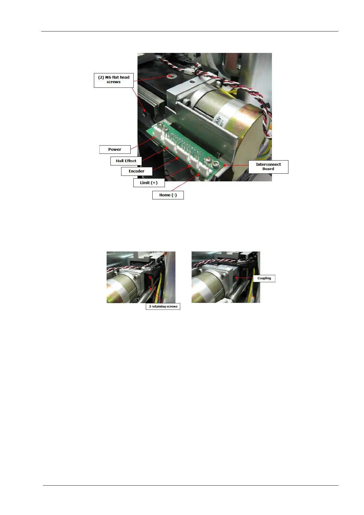
Figure 181: Removing Y-axis servo motor and coupling
7. Use the flat head screwdriver to remove 2 retaining screws securing the tool changer
electrical connector and disconnect.
8. Slide Y tube assembly forward independently of servo motor assembly exposing the
coupling on the right side.
Figure 182: Removing Y-axis servo motor and coupling
9. Loosen but do not remove the clamp screw on the ball screw end of the coupling (with
the power off and cables disconnected the coupling may be slightly rotated manually
in order to access the clamp screw).
Attempting to remove motor with coupling attached to the ball screw will break or
damage coupling.
10. Use a 4 mm Allen key and remove (4) screws securing the servo motor to the motor
mount and carefully slide the motor out of chassis.