2 Basic repair procedures Chapter E: Basic repair procedures
170 Planmeca PlanMill 40 Technical manual
Figure 183: Removing Y-axis servo motor and coupling
Install
Installation of a new servo motor requires a careful alignment procedure, described
in the following steps. Failure to follow the alignment procedure can cause prema-
ture failure of mill components.
1. If not already installed, install the servo coupling on servo motor shaft.
The proper distance between the motor face and the Y-axis servo coupling is 5 mm.
2. Torque to 2.03 nm (18 in-lbs).
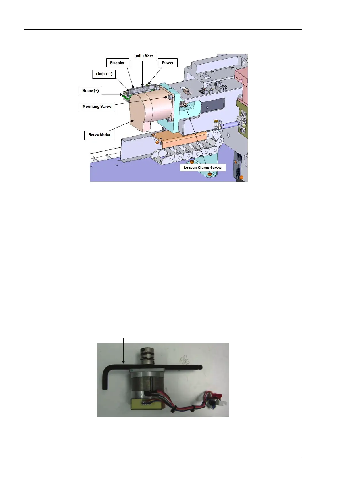
You can use the 5 mm Allen key as a spacer to set the coupling on the motor shaft.
Figure 184: Setting coupling spacing
3. Install the servo motor and coupling onto the motor mount and ball screw and snug
the (4) mounting screws attaching the servo to the motor mount.
4. Snug the coupling clamp screw (on ball screw end of the coupling).
5 mm Allen key
used as spacer