Chapter E: Basic repair procedures 2 Basic repair procedures
Technical manual Planmeca PlanMill 40 171
5. Loosen the (4) mounting screws on servo to allow the motor to center on the shaft.
6. Retighten the (4) mounting screws to 2.03 nm (18 in-lbs).
7. Loosen the coupling clamp screw (on ball screw end), this allows the coupling to
relieve any axial stress and re-torque to 2.03 nm (18 in-lbs).
8. Connect servo motor encoder, hall-effect and power cables to the interconnect board.
Both the hall-effect and encoder connectors are 5-pin connectors; the hall-effect
(blue connector with 5 wires) goes in the middle. Inserting the connectors wrong
can cause severe damage to the motor or amplifier.
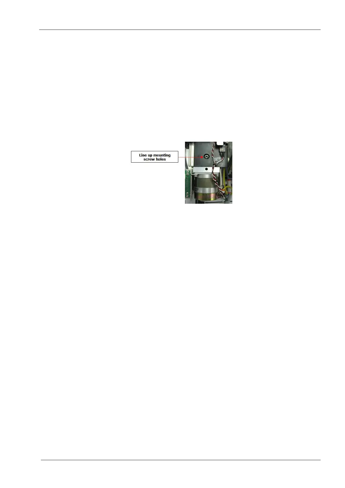
9. Slide the tool changer assembly back so that the mounting screw holes are in line.
Figure 185: Installing Y-axis servo motor with coupling
10. Tighten the (2) M6 flathead mounting screws to 5.2 nm (46 in-lbs).
The top mounting screw is much shorter than the left side mounting screw.
11. Reinstall top cover, side panel and rear cover, see section 2.1 "Mill covers" on page
94.
Verify
1. On mill screen touch Maintenance Icon.
2. Select Advanced and enter passcode 1234.
3. Select Technician Console.
4. Select High Level button.
5. Select the Mechanical Control box.
6. Select Open Tool Changer button.
7. Select the Axis Positions box.
8. Move the Y-axis forward and back to its limits, verify free non-binding operation for full
travel.
9. Select the Open Tool Changer button; verify smooth operation of tool changer.
10. Navigate to: Technician Console --> Motion Diagnostics --> Encoder Check.