Chapter E: Basic repair procedures 2 Basic repair procedures
Technical manual Planmeca PlanMill 40 101
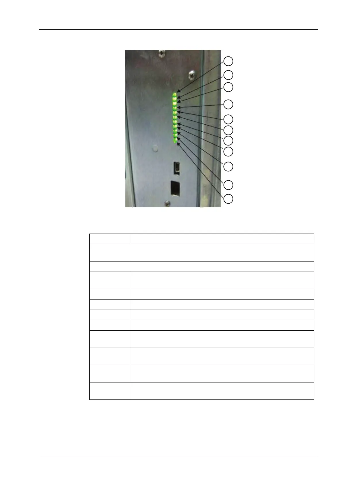
Figure 83: LED indications
5. Verify system initializes and homes all axes with no errors.
Table 23: LED descriptions
LED number Description
1 +5V STATUS LED POWER - power status to the LEDs around the
grind chamber
2 +5V I/O POWER - power status to the I/O circuits in the mill
3 +5V ENC POWER - power status to the encoders for the motors in the
mill
4 +5V STANDBY POWER - power status of the 5V standby bus
5 +5V SWITCHED - power status of the 5V Switches bus
6 +12V SWITCHED - power status of the +12V Switches bus
7 -12V SWITCHED - power status of the -12V Switches bus
8 HEART BEAT INDICATOR - flashing indicates the micro controller is
working
9 FAN SPEED INDICATION - insdicates that the fan in the electronics
box is spinning at a good RPM
10 +42V MOTOR POWER SUPPLY - power status of the motor power
supply
11 +12V PUMP/FAN POWER - power status of the fluid pump and fan
power