2 Basic repair procedures Chapter E: Basic repair procedures
162 Planmeca PlanMill 40 Technical manual
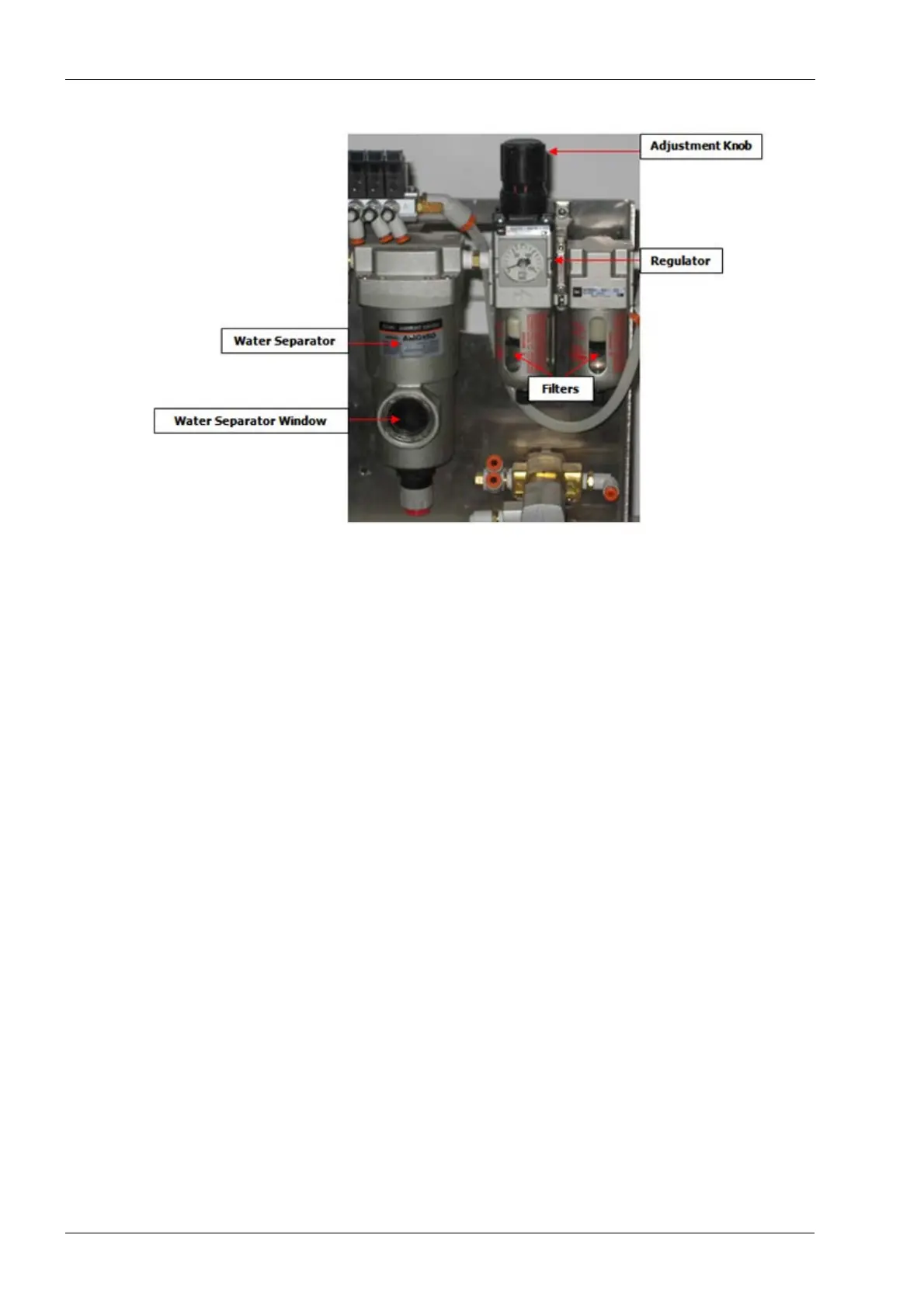
Figure 173: Regulator, filter and water separator assembly
Tools required
• metric Allen key set
Removal
1. Remove pneumatic assembly, see section 2.12.1 "Pneumatics assembly" on page
155.
2. Tag and disconnect the 6.35 mm (¼”) supply tube located to the left of the regulator
unit.
3. Tag and disconnect the (3) 6.35 mm (¼”) exit tubes located to the right of the water
separator unit.
4. Remove the upper bracket screw securing the regulator/separator assembly from
pneumatics assembly.
5. Lift free from the pneumatic assembly.
Install
1. Position regulator/separator assembly in place on pneumatics assembly and secure
with mounting screw.
2. Connect pneumatic tubes to appropriate locations on regulator/separator assembly.
3. Reconnect the air supply line and apply pressurized air.
4. Set regulator to 3.45 bar (50 psi).
5. Verify that there are no air leaks.
6. Reinstall rear cover, side panel and top cover, see section 2.1 "Mill covers" on page
94.
Adjusting pressure regulator
Pressure regulator can be adjusted by setting the adjusting knob.