2 Basic repair procedures Chapter E: Basic repair procedures
198 Planmeca PlanMill 40 Technical manual
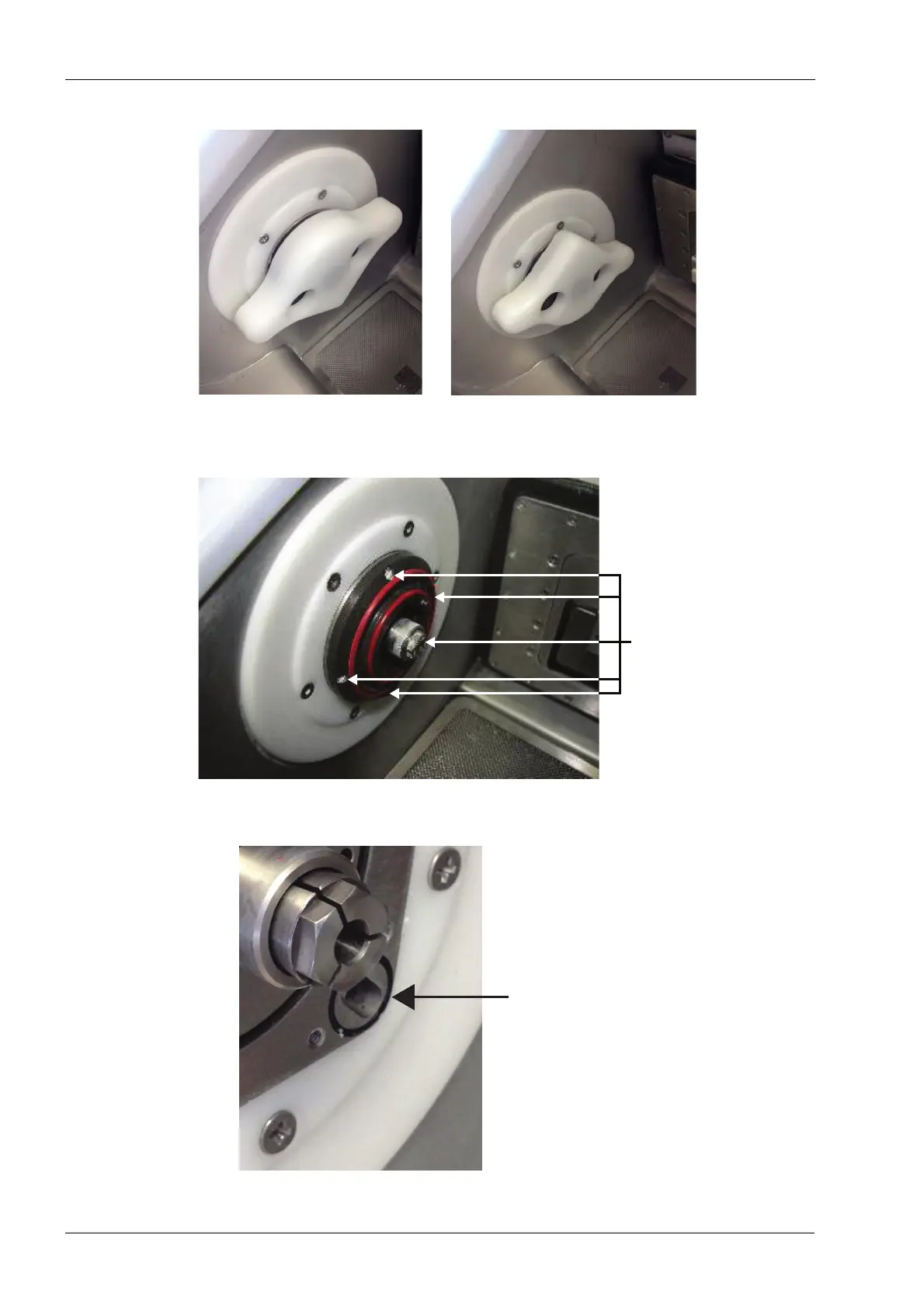
Figure 219: Nozzle cap removal
3. Use the #00 Philips Screwdriver to remove the 5 screws that secure the quick release
adapter to the spindle housing.
Figure 220: Quick release adapter removal
4. Remove the quick release adapter from the face of the spindle housing.
Figure 221: Ensure black O-ring remains in groove
Ensure black
O-ring remains
in groove