2 Maintenance procedures Chapter B: Preventive maintenance
40 Planmeca PlanMill 40 Technical manual
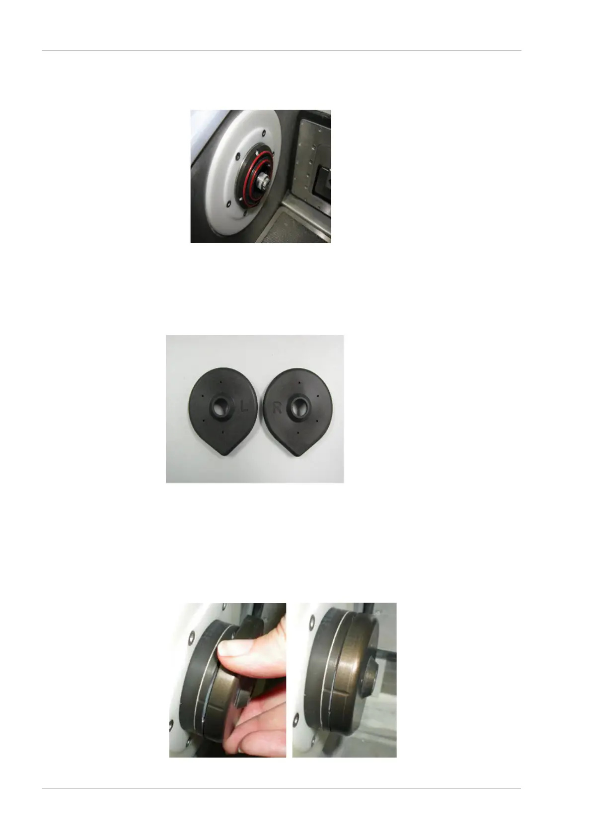
15. Remove and check the condition of the red O-rings. If they are torn or worn-out,
replace them. If O-rings are in good shape, just wipe them with a damp paper towel to
remove any residue.
16. Clean the nozzle. Use a soft nylon brush (Do not use wire brush!) to dislodge any
build-up from the grooves of the nozzle. Do not remove the six (6) Philips screws on
the housings.
17. Replace the spindle cap. Note the L or an R on the spindle caps to denote on which
side of the mill it belongs.
Figure 29: Left and right spindle caps
The alignment grooves on the spindle cap and spindle housing and the pointed extension
on the spindle cap. Use these for proper alignment.
18. To attach the spindle cap, align the grooves so that the spindle cap extension is
pointing upwards.
19. Then turn the spindle cap clockwise until the extension points downward and the cap
groove aligns with the housing groove.