PG-FP6 V1.06 4. Usage of the FP6 Terminal
R20UT4469EJ0800 Rev.8.00 Page 49 of 188
Oct.01.21
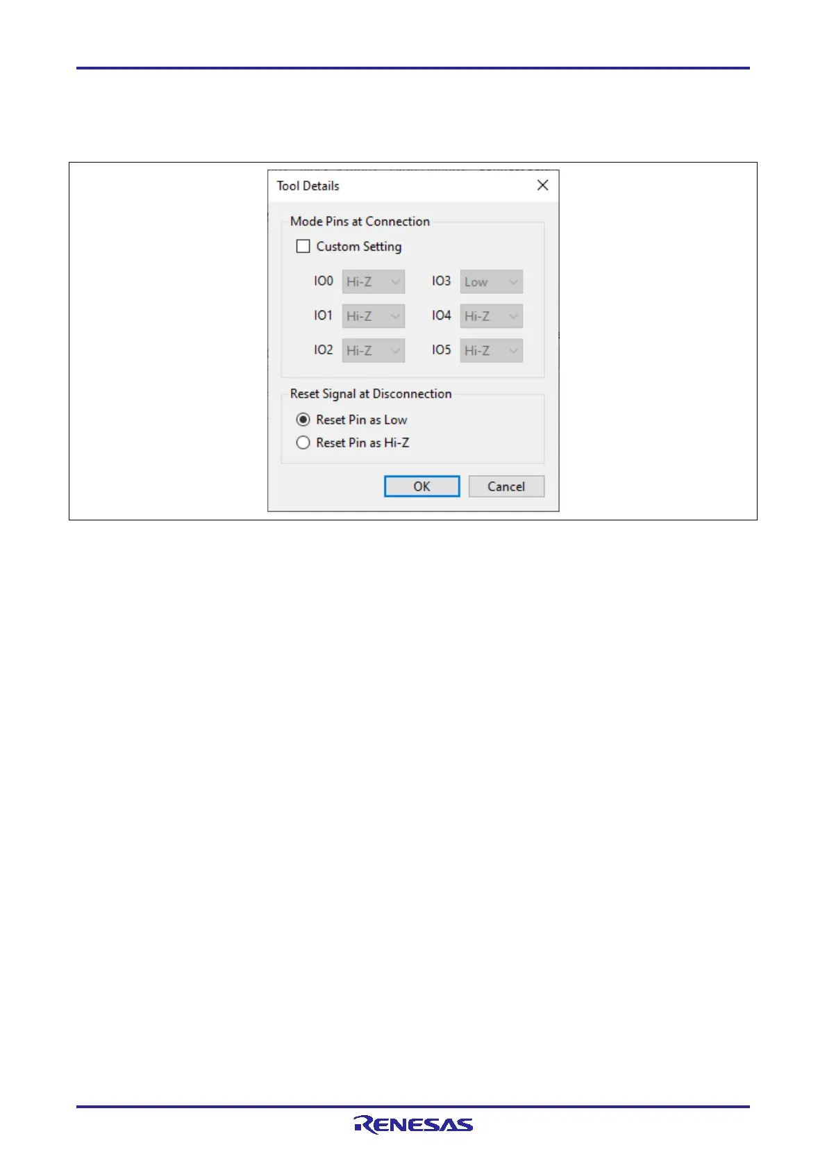
• Tool Details
Click on this button to open the [Tool Details] dialog box, which enables setting of the states of the mode
pins at the time of connection and of the reset pin at the time of disconnection.
Figure 4.11 [Tool Details] Dialog Box
• [Mode Pins at Connection]
To modify the levels on the mode pins (I/O pins) at the time of connection, select “Custom Setting” and
set IO0 to IO5. You can then change the pin settings to the high-impedance state or to the high or low
output level.
Remark: Depending on the target device, certain selections may not be available.
For pin assignments, refer to Table 10.3, Pin Configuration of the Target Connector (14-Pin Type),
and Table 10.4, Pin Configuration of the Target Connector (20-Pin Type).
• [Reset Signal at Disconnection]
Select the state of the reset pin at disconnection from the target device.
Reset Pin as Low
After disconnection, a low-level signal is continuously output from the RESET pin.
Reset Pin as Hi-Z
After disconnection, the RESET pin is held low for a short time and then placed in a Hi-Z state. This
setting is used when making the target device operate after completion of the FP6 processing.
(B) Power Supply
• Power Supply from FP6
Select whether power should be supplied from the FP6 or the target system during the process of
connecting the target device.
Remark: We recommend supplying power from the target system to the MCU for on-board programming.
Specify the voltage value within the range of 1.8 V to 5.5 V.
Caution: The voltage value should meet the operating conditions of the target device and target system.

 Loading...


